This thread has been locked.

If you have a related question, please click the "Ask a related question" button in the top right corner. The newly created question will be automatically linked to this question.

LMH1297: Glitches are observed at 4K@60fps. Working fine with 4K@30fps

Part Number: LMH1297

Hi TI Team,

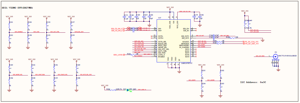
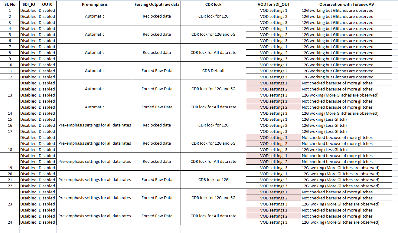
We are using LMH1297 for 12G SDI OUT application using Zynq US+ MPSoC. When we use 12G SDI to HDMI Converter from BMD ( Teranex Mini SDI - HDMI 12G) to monitor the output, lock is happening in module for 4K 30fps and  we are able to see the output in monitor as well. But for 4K@60fps BMD module itself is not locking. Then we tried connecting 12G SDI output with Teranex Standard converter AV, We are able to observe output at 4K 60fps but with lot of glitches. I have attached the schematics section, could you please review the same and help us to find the issue. Reference clock given is 148.5MHz single clock to GTH bank.

Best Regards,

Vyshnav krishnan  

  • Greetings Vyshnav,

    I could vaguely see your schematic. It seems you are using the device in cable driver mode. In this mode, SDI_OUT 75-ohm driver is used.

    SDI_IO in your setup is acting like a cable driver as well(in pin mode and cable driver mode we cannot turn off this output). However, this output is not terminated. Also, i believe you are enabling OUT0 100-ohm output through OUT0_SEL as well and this output is not terminated.

    In your application, i was expecting that you would use SDI_IO as cable driver and use SDI_OUT_SEL to disable the 2nd cable driver by floating this pin. Also, we should float OUT0_SEL to disable 100-ohm output. With these outputs un-terminated and active there is high reflections. It would be good if we can take care of these to see if this takes care of the issue you  are seeing. Also, please send me a pdf copy of your schematic so it would be more readable. We regularly use 59.94 or 60Hz frame and have not experienced this issue.

    Regards,, Nasser 

  • Hi Nasser,

    Thank you for your quick response. With same configuration, we are able to get 12G-SDI output in our development platform. As PCBs are fabricated already, is there any way to disable these signals.? (SDI_IO and OUT0) I think through I2C configuration its possible .? Also by adjusting Pre-emphasis settings is it possible to tune the output.?  Since it's a custom project, I cannot share the schematics. Please help us to proceed further.

    Thanks & Regards, 

    Vyshnav Krishnan

  • Hi Vishnav,

    1). Yes for sure through the I2C you can control these and turn off or power down both OUT0 and SDI_IO driver.

    2). One th9ing you can try, OUT0_SEL is pin 4. Maybe you can run an experiment and use a blue wire to pull this pin high. This may improve things.

    Regards,, Nasser

  • Hi Nasser,

    1. We tried turning off OUT0 driver and we are getting same observation.

    2. Also tried disabling SDI_IO driver as well. But register override was not happening. We are able to read the register values. 

    We are planning to control pre-emphasis and slew rate values and check. Could you please suggest best tuning settings or any other method to solve this issue. 

    Regards,

    Vyshnav

  • Hi Vyshnav,

    Through register settings you should be able to turn off SDI_IO driver. Please refer to the LMH1297 programming guide. If you don't have access to this, please refer to the link below to request this information:

    https://www.ti.com/drr/opn/LMH1297-DESIGN

    In default mode, default should have optimum pre-emphasis and slew rate. You can refer to the programming guide for changing some of these options.

    Regards,, Nasser

  • Hi Nasser,

    We have compared the register set of LMH1297 on both working and non-working boards and found almost all registers are similar except VEO and HEO. Below are the deviations observed register set and corresponding values.

    REGISTER NAME         Default         Working          Non-working
    0x27 HEO                        0x00              0x29                  0x32               decimal value/64
                                                                  0.64                  0.78
    0x28 VEO                        0x00              0x62                   0x6c               decimal value * 3.125 mv
                                                                  306.35                337.5

    But when we observe the obtained value, the eye opening seems to be good in non-working board. So does this signifies that incoming signal to IC is proper and we need to debug on the output side..? If yes, what and all parameters we need to take care.?

    Thanks & Regards,

    Vyshnav Krishnan

  • Hi Vyshnav,

    I agree with your assessment. The non-working unit seems to have a better eye opening. Please make sure CDR is lockd in both cases. 

    Given your comments, i would consider looking at de-emphasis at the output. You may want to reduce or not use de-emphasis. If you have scope, you can monitor 100-ohm output waveform at the receiver side. Also, if possible change the receiver since may be there is an issue on the receiver attached to the 100-ohm output of the non-working unit.

    Regards,, Nasser

  • Hi Nasser,

    1. It's been observed that CDR is locked in both the cases. 

    2. Checking de-emphasis will not be possible since, we are using Teranex mini SDI - HDMI 12G device for our testing purpose. The 12G SDI output signals will be processed by this module.

    3. Currently we are testing by tuning the IC by changing few settings. I request you to review the observations and help us once we complete that.

    with current observation, can we conclude that input to the IC from FPGA is proper..? How to verify the input to IC is good and glitches free. 

    Thanks & Regards,

    Vyshnav Krishnan

  • Hi Nasser,

    Please go through the test observation we obtained till now. In all the cases we are getting glitches for 12G SDI output. In some cases it seems to be more.

    For test case 15,16,17 and 18 we got less glitches. Also suggest any method to solve this issue.

    Regards,

    Vyshnav Krishnan

  • Hi Vyshnav,

    For all of your test, you have used BMD at 4K@60fps. Do you happen to have another monitor or 12G SDI camera from another vendor beside BMD?

    I think this could be a compatibility issue with BMD 12G SDI @ 60fps. Can you please try another SDI sink part?

    Regards,, Nasser

  • Hi Nasser,

    When we restrict IC to lock 12G SDI input only, the Lock LED is properly glowing only for 12G SDI mode. This made us to check whether extra length of signal pin of SDI Connector is acting as stub. The PCB thickness is 2mm and connector pin length is 3.1mm. Since signals are routed on top there will be a stub of 118mils.

    So we cut the connector pin by 1.5mm and mounted. Currently we are able to get the output properly for 12G SDI without any glitches with both BMD modules. I would like to say thank you for your continuous support.

    I have one more query, whether LMH1297 IC can detect the resolution supported by the monitor connected to it (Sink device capabilities). ? Is there any register which we can read and find this info. ?

    Best Regards,

    Vyshnav Krishnan

  • Hi Vyshnav,

    Glad you were able to find the root cause of the problem. At 12G SDI, we use surface mount BNC. Alternative we have used through hole BNC as well but we should avoid stub by putting the device on the same side as BNC pin - to avoid stub. Also, BNC anti-pad has to be done carefully to make sure there is no negative side effects. Normally your BNC vendor would provide you with PCB layout and anti-pad.

    As it relates to your question, LMH1297 can detect data rate but not the resolution.

    Regards,, Nasser

  • Hi Nasser,

    So we cannot switch the output according to the connected monitor by understanding the capabilities of it.?

    Regards,

    Vyshnav Krishnan

  • Hi Vyshnav,

    Your understanding is correct.

    Regards,, Nasser

  • Hi Nasser,

    Thank you so much for your support and guidance.

    Best Regards,

    Vyshnav Krishnan