This thread has been locked.

If you have a related question, please click the "Ask a related question" button in the top right corner. The newly created question will be automatically linked to this question.

DS90UB954-Q1: 0x7A 0x7B

Part Number: DS90UB954-Q1

Hi Sir 

When I increase frame rate from 18fps to 22fps ,The image will have noise issue 

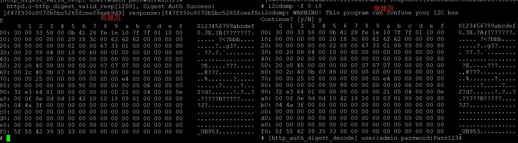
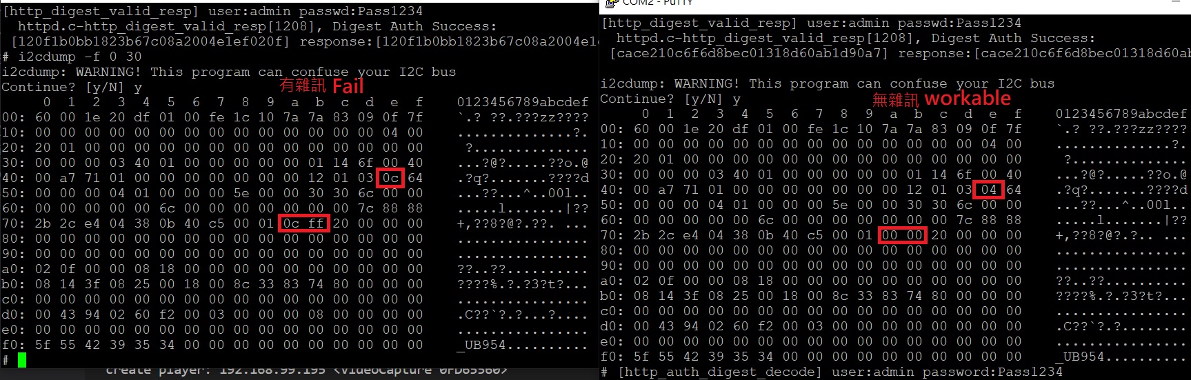
"I saw 954 register 0x7A and 0x7B have error message" and 953 all register is the same between fail and normal condition

May I learn from you how to solve this issue ,we use STP for this application 

if 0x7A or 0x7B have error message ,it means the communication error happen between 954 and 953 ? 

Below is 954 normal and fail register 

Below is 953 normal and fail register ,seems like no problem and without any error

  • Hello Kaileh,

    It looks like your first image did not post. Can you please try again with the 954 reg dump image? Also can you please give more details on your system? Do you have 1 or 2 cameras? What is the CSI-2 clock rate on the 953 input side under the 18 and 22fps configurations?

    Best Regards,

    Casey 

  • Hi Casey

    Our system use 1 camera ,STP mode ,Sync mode ,clock 24MHz to CMOS sensor

    DS90UB954 register is below ,only 7A / 7B / 4E are different 

    When I use 953 to do pattern gen ,the image is below ,seems like it's abnormal 

  • Hello Kalieh,

    The error registers do indicate CSI-2 errors on the 954 side but strangely no other errors related to the FPD-Link connection such as parity errors, or loss of lock. This usually means the error is coming from the 953 input side (imager CSI-2 input), but the 953 does not appear to be flagging any errors which is very unusual. Can you please double check once more by reading back the 953 registers several times to see if any error flags are showing up in the CSI-2 registers when the issue is occurring? 

    If there are still none, then I would suggest double checking your 954 schematic and HW design to see if there are any issues like voltage rail below recommended spec or issues with the 954 power sequence. 

    The 953 PATGEN picture you posted below seems to have the incorrect dimensions. Is that a full image capture? The 954 is reporting the correct full frame dimensions in registers 0x73-0x76 so I suspect that if the image dimensions are showing up incorrectly in the final capture it is related to the CSI-2 RX configuration and video pipeline rather than the 953/954. The colors look normal based on the data type you are using (RAW12) and the reference CSI-2 color bar pattern bytes. You can use the Analog LaunchPad GUI to easily program of develop code for 954 or 953 PATGEN if you are having issues with that. 

    Best Regards,

    Casey 

  • Hi Casey 

    We check several time ,the register only change on 954

    Fail registers are below 

    0x4E = 0C

    0X7A = 0C

    0X7B = FF

    0xDB = 08 

    If We use CSI-2 RAW12 data type ,have anything need to take care on 953 and 954?

    Thanks

  • Hello Kaileh,

    There is no configuration needed based on the CSI-2 data type when using 953->954. Can you please measure the power rails provided to 954 to check the DC level and noise is meeting the datasheet spec? Also please confirm the power sequence is matching the power sequence specified in the datasheet. 

    If you would like to post your schematics here, we can review them to check for any issues. 

    Best Regards,

    Casey 

  • Hi Casey 

    Below video is our test method 

    When we use RAW12 Pattern gen from 953 ,the fail register issue will be disappear 

    I just want to check the 953 and 954 function is normally and test pattern is correct 

    and attached file is 953/954 schematic 

    953.pdf

    954.pdf

  • Hello Kaileh,

    The fact that it works well with PATGEN and not with the imager seems to indicate that the imager configuration (CSI-2 source to 953 is not configured correctly or is using an incompatible lane rate for the 953). 

    But there is another major issue I can see in the schematics and that is that it looks like the FPD-Link interface is routed through an RJ11 connector. These devices are not designed or qualified to support RJ11 cable assembly. The RJ11 jack and assembly is designed to support low speed ~24Mbps signaling. The 954/953 devices use 4Gbps line rate between SER and DES, which requires high qualify, low loss cabling/channel between the devices. I would recommend updating the design to use a cabling/connector assembly with Rosenberger HSD/Dacar 535 or similar 

    https://training.ti.com/common-connectors-and-cables-automotive-applications?context=1134310-1139223-1134171 

    Best Regards,

    Casey