This thread has been locked.

If you have a related question, please click the "Ask a related question" button in the top right corner. The newly created question will be automatically linked to this question.

DS90UB948-Q1: HSYNC timing stability with external clock

Part Number: DS90UB948-Q1
Other Parts Discussed in Thread: SN65DSI84, LMK61E0M

Hello,

We have the following configuration:

MIPI DSI => DS90UB941 => 1 single ended FPD link => DS90UB948 => LVDS screen (800x1200 at 60 fps)

PCLK = 72MHz

When using an external clock for the serialiser (DS90UB941), what is the timing tolerance in terms of pixel clock on the LVDS ?

I did some measurements and i have the following (in Pixel clock):

Horizontal Front Porch / Horizontal Sync / Horizontal back porch / data

56 / 24 / 24 / 799 = 903

55 / 24 / 24 / 800 = 903

58 / 24 / 23 / 800 = 905

When doing the same measurement with the MIPI clock of the DS90UB941, i have stable timing, in line with our MIPI configuration:

72 / 24 / 24 / 800 = 920

Why do we have different timing on the Front porch, and why the timing are not stable with the external clock ?

Is it the retiming between the MIPI clock and the external clock domain ?

Is it possible to improve it ?

We also have the same behavior (screen flickering) with the SN65DSI84 (MIPI to LVDS bridge).

Thanks,

Best regards,

Alexandre

  • Hi Alexandre,

    Aaron will answer this question tomorrow, thank you for your patience.

    Regards,

    Michael W.

  • Hi Alexandre,

    The PCLK has ±100ppm. Normally, a few pixel discrepancy shouldn't be a problem. You need to make sure that you have the exact video timing from your display and program the correct value on the serializer side.

    Aaron

  • Hello Aaron,

    Just to make sure my understanding is correct:

    I should program the DSI indirect registers as follow:

    0x20 (4) = 0 => 0 : Don't regenerate original VS/HS timing

    0x30 = 0

    0x31 = 18h => 24 Hsync pulses

    0x32 = 0

    0x33 = 03h => 3 VSYNC pulses

    Is there any other register to configure ?

    Alexandre

  • Hello Aaron,

    We try the configuration, describe above, and we stille have the flickering

  • Hi Alexandre,

    Are you using the external clock source for the 941AS? Can you share me your schematic? Thanks.

    Aaron

  • Hi Aaron,

    Yes, we are using an external clock source for the 941AS. The SerDes link is good, we don't have any loss of lock.

    How do i share the schematic in private ?

    Alexandre

  • Alexandre,

    The instability in the HFP in external timing mode is due to the PPM difference between the video PCLK from the DSI interface, and the REFCLK frequency you are providing. The 941AS has a line buffer to store DSI data before passing it off to the FPD III domain which in this case is clocked from the REFCLK which you are providing. If there is any frequency difference between the PCLK values in those two domains, then the device has to compensate the offset to prevent the FIFO from overflowing or underrunning. If the REFCLK you provide is slower than the video PCLK, then the 941AS will start removing pixels from the HFP to compensate the PPM offset. If the REFCLK is faster than the video PCLK, then the device will add pixels to the HFP to compensate. 

    Also, you may see instability of a couple pixels line to line in this configuration based on the characteristic of the DSI source settings and if you have applied any M/N divider to the REFCLK through registers. Basically this is expected behavior and can be adjusted by changing your REFCLK value 

    Best Regards,

    Casey

  • Hello Casey,

    Thanks for the explanation,

    Do you have an application note which explains how to set the divider registers the FIFO size and the REFCLK value ?

    Since the DSI clock is dependant of the displays caracteristics, it is difficult to match exactly the Pixel clock frequency from the DSI with the REFLCLK and the divider.

    Below our last tests:

    • I try with an arbitrary signal generator (below 40ps jitter) with the pixel clock frequency up to 3 decimal precision  => screen is still flickering
    • FIFO (DSI_SYNC_DLY 0x34 and 0x35) with half the total horizontal length => screen is black
    • FIFO (DSI_SYNC_DLY) =  total blanking => screen is black
    • FIFO (DSI_SYNC_DLY) =  HSYNC +  BACK PORCH => screen is still flickering
    • FIFO (DSI_SYNC_DLY) =  HSYNC  => screen is still flickering
    • FIFO (DSI_SYNC_DLY) =   BACK PORCH => screen is still flickering
    • Regarding the M/N dividers the automatic values are 0x3A = 02h and 0x3B = 03h 
    • What is the exact formula to apply ? it looks like : Fpxclk = Fdsi * nbre lane * M / (8 * N)
    • I try different configuration to get close to our REFCLK, but i have at least 0.1MHz difference, and i don't see any more or less flickering

    any idea ?

    Best regards,

    Alexandre


  • Hello Alexandre,

    We actually are working on an app note for this but it won't be available until later this year as the topic is quite complex to cover in detail. Actually based on your feedback here I'm not positive that the issue is related to the clocking scheme or simply the timing not matching the display tolerance. 

    Does the display work properly with no flickering in PCLK from DSI clock mode (no external REFCLK)?

    Can you share the display datasheet or timing tolerance table?

    Can you also share the DSI video parameters which are being provided by the DSI source?

    Have you verified this screen to not flicker when driving it with internal PATGEN from the 941AS without the DSI source?

    Best Regards,

    Casey 

  • Hello Casey,

    When in DSI CLOCK mode, the display works properly, but, since the DSI jitter is out of your FPD Link jitter requirement, we have some flickering due to the loss of the SerDes lock.

    If i drive the screen with the PATGEN, with custom timing, it works well.

    If i drive the screen with the PATGEN, with DSI timing and external clock (with internal also), i have constant flickering

    Best regards,

    Alexandre

  • Below the final screen configuration

    My preliminary results comes from another configuration, which provides the same behaviour.

    Parameter Min Typ Max Unit Our config
    DCLK Frequency 72.0 76.1 79.8 MHz
    Horizontal Display Area  800 DCLK 800
    Horizontal Back Porch 80 (note) DCLK 80
    Horizontal Pulse Width 1 70 DCLK 24
    Horizontal Front Porch  30 80 120 DCLK 56
    One Line Time  910 960 1000 DCLK 960
    Vertical Display Area  1280 H 1280
    Vertical Back Porch 23 (note) H 20
    Vertical Pulse Width  1 20 H 3
    Vertical Front Porch 15 18 27 H 18
    One Frame Time  1318 1321 1330 H 1321

    Note: HBP include HPW, and VBP include VPW

    Best regards,

    Alexandre

  • Alexandre,

    I'm not fully understanding your comments so let me ask some follow on questions:

    When in DSI CLOCK mode, the display works properly, but, since the DSI jitter is out of your FPD Link jitter requirement, we have some flickering due to the loss of the SerDes lock.

    [Casey] Ok 

    If i drive the screen with the PATGEN, with custom timing, it works well.

    [Casey] When you say custom timing, what to you mean here? Do you mean PATGEN with internal timing generation and internal clock? If so, then what timing parameters are you setting and what clock rate?

    If i drive the screen with the PATGEN, with DSI timing and external clock (with internal also), i have constant flickering

    [Casey] I think you are saying PATGEN with external timing (and clock) based on the DSI input which is going into 941AS during the test. There is no way to enable external timing and internal clock. If the PATGEN is in external timing mode it will always use external clock as well

    What happens if you drive PATGEN with internal timing and external clock? (External clock being the clock from REFCLK, not the DSI clock). Does it flicker in that condition? 

    By the way, how are you measuring the resultant horizontal timing intervals getting to the display? How did you determine the specific pixel values?

    What I suspect is happening is that your DSI source is providing unstable timing that doesn't meet the DPI timing of the display consistently. This can result from a number of different things, but we give a detailed example of this phenomenon in this app note: https://www.ti.com/lit/pdf/snla356 

    See section 4.3 

    Best Regards,

    Casey 

  • If i drive the screen with the PATGEN, with custom timing, it works well.

    [Casey] When you say custom timing, what to you mean here? Do you mean PATGEN with internal timing generation and internal clock? If so, then what timing parameters are you setting and what clock rate?

    [Alex]  In terms of configuration we have:

    - external pixel clock when using internal timing
    - the Pattern Generator uses external video timing from the pixel
    clock, Data Enable, Horizontal Sync, and Vertical Sync signals.
    => KO = Flickering (0x65 0x08)
    - external pixel clock when using internal timing.
    - The Pattern Generator creates its own video timing as configured
    in the Pattern Generator Total Frame Size, Active Frame Size,
    Horizontal Sync Width, Vertical Sync Width, Horizontal Back Porch,
    Vertical Back Porch, and Sync Configuration registers.
    => OK (0x65 0x0C)
    - Selects the internal divided clock when using internal timing
    - The Pattern Generator creates its own video timing as configured
    in the Pattern Generator Total Frame Size, Active Frame Size,
    Horizontal Sync Width, Vertical Sync Width, Horizontal Back Porch,
    Vertical Back Porch, and Sync Configuration registers.
    => OK (0x65 0x04)
    - Selects the internal divided clock when using internal timing
    - the Pattern Generator uses external video timing from the pixel
    clock, Data Enable, Horizontal Sync, and Vertical Sync signals.
    => KO = Flickering (0x65 0x00)

    By the way, how are you measuring the resultant horizontal timing intervals getting to the display? How did you determine the specific pixel values?

    [Alex] I measure the number of clock period during the HSYNC event, Front porch, display data .... 

    What I suspect is happening is that your DSI source is providing unstable timing that doesn't meet the DPI timing of the display consistently. This can result from a number of different things, but we give a detailed example of this phenomenon in this app note: https://www.ti.com/lit/pdf/snla356 

    See section 4.3 

    [Alex] I already look at your app note. But when i am using DSI clock, the timing on the LVDS output perfectly match.

    Regarding the DSI protocol analysis, we don't have a DSI analyser.

    Regarding the DSI status files, a first read gives:

    0x0F 0x7f
    0x10 0x04
    0x11 0x04
    0x12 0x18
    0x13 0x04

    Then

    0x0F 0x1f
    0x10 0x00
    0x11 0x00
    0x12 0x00
    0x13 0x00

    Best regards,
    Alexandre
  • Hello Alexandre,

    0x65 = 0x08 and 0x65 = 0x00 are equivalent settings. They both mean that the PATGEN uses external timing and external PCLK since 0x65[4] has no effect when 0x65[3] = 0. 

    So what the PATGEN results indicate is that if you generate the video timing internally and use either internal or external clock, the video is working fine. Only when the timing is extracted from the DSI source do you see issues which is again suggesting that something unexpected is happening in your DSI source side packet structure. 

    For this question:

    By the way, how are you measuring the resultant horizontal timing intervals getting to the display? How did you determine the specific pixel values?

    [Alex] I measure the number of clock period during the HSYNC event, Front porch, display data. 

    [Casey] But my question was how specifically are you taking this measurement? Because you mentioned that the deserializer is 948 which is OpenLDI output. So HSYNC/VSYNC are embedded into the LVDS data stream and do not come out to individual pins. Also DSI outputs HSYNC/VSYNC in packets so they are not discrete signals. How are you probing this?

    I think to debug this further you do need to get the right equipment to properly analyze your DSI output stream as described in the application note to help identify at a more detailed level what you are providing from the source side. 

    If you have already adjusted the REFCLK up or down in frequency until the sync timing coming out matches the sync timing when you are using PATGEN, then the display should work. If the timing is unstable in this condition, then it probably has to do with how and where the source is placing LP->HS transitions into the BLLP periods of the data. You will get more stable timing if you use HS blanking packets instead of LP->HS to denote horizontal blanking periods. 

    Best Regards,

    Casey 

  • Hello Casey,

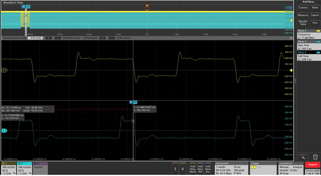
    Regarding the pixel measurement of LVDS signals, below a screen capture.

    I measure the number of rise time transition on the clock during the HSYNC. I check that the data corresponds to the HSYNC.

    Regarding blanking it is easier since there is no data.

    The measurement are done on the channel 2 of the LVDS and the clock channel

    The DSI LP/HS transition is done at every frame, not every horizontal line. We can observe the transition with the oscilloscope.

    I can also observe the blanking on MIPI lane, but i didn't measure it and its stability.

    I think to debug this further you do need to get the right equipment to properly analyze your DSI output stream as described in the application note to help identify at a more detailed level what you are providing from the source side. 

    Do you have a reference of a "low cost" equipment for this kind of measurement ?

    You will get more stable timing if you use HS blanking packets instead of LP->HS to denote horizontal blanking periods. 

    => what do you mean ? Is it something to configure on the DSI source (Snapdragon micro) or at the serialiser side ?

    If the timing with the LP/HS transitions is unstable, then why is it stable when using the MIPI clock for the serialiser ?

    Best regards,

    Alexandre

  • Hey Alex,

    Ok, I'm still confused on how you are taking that measurement and differentiating between HSYNC/VSYNC/DE... I don't see how you are doing that from the scope shot but in any case, here's another question for you.

    See you mentioned that in PCLK from DSI clock mode the display is not flickering, but you also said when you do PATGEN with external timing 0x65 = 0x08, that the video flickers. This should not be the case if the DSI timing is correct. What are you setting for BRIDGE_CLK_MODE when you do this test? Does it change if you set 00 vs 01?

    Only other thing I can think is that the REFCLK frequency you are applying is off in frequency from the average video PCLK from the source. In PCLK from DSI clock mode you are saying it is working correctly. Can you measure the exact PCLK frequency on the 948 side when you are in this mode? Is that frequency equal to what you are applying to the REFCLK pin when you go to external REFCLK mode? 

    Best Regards,

    Casey 

  • Hello Casey,

    If you look at the screen below, we see the transition from vertical to horizontal transition. Without a dedicated equipment, manual reading is the only option. Like I2C or UART in the old days.

    Regarding the REFCLK frequency, what is the acceptable tolerance from the source PCLK ?

    Does it mean we need to first check with oscillator suppliers the available frequencies ? and find the best compromise between the screen timing and the frequency ?

    Will it be interesting to have a programmable PLL with jitter attenuator synchronised with the MIPI clock ?

    I will make a new measurement with our signal generator  on Monday and apply the exact clock of the DSI clock mode.

    Best regards,

    Alexandre

  • Hi Casey,

    We have additionnal questions:

    Why the LVDS HSYNC is stable when the MIPI Clock is used and become unstable when the external ref clock is used?

    Regarding MIPI HS blanking instead of LP-> HS, we are already applying this. We see the LP11 transition every frame (around 16ms) and we see the blanking during each horizontal period.

    Otherwise, is it more interesting to use the MIPI burst mode ?

    Then what are the main registers to configure ?

    I make new tests with a programmable signal generator and program it with the PCLK we have in DSI clock mode.

    I assume a 30kHz deviation is acceptable for SSC.

    I don't see any improvements.

    Best regards,

    Alexandre

  • Hello Alexandre,

    During the device qualification, we used LMK61E0M as the REFCLK source for external REFCLK mode which allows for programming a precise and flexible frequency based on system tuning (that is also included as an optional stuffing component on the 941AS EVM). That may be worth considering here as an option for your system design.

    We have not seen any issues with HSYNC timing stability outside of the case where the DSI timing is unstable, so the issue that is happening here in your system is still unclear. You mentioned that you measured the PCLK rate in DSI clock mode and then applied the exact same PCLK rate to the REFCLK for external clock mode? What was the measured frequency?

    You mentioned that SSC is being applied in your latest post? That sounds like it very well could be related. Can you please try disabling SSC and use a fixed frequency to see if the issue goes away?

    Best Regards,

    Casey 

  • Hello Casey,

    Below the measured frequency in DSI clock mode:

    • Min = 75.837942 MHz
    • Max = 75.956176 MHz
    • Average = 75.897059 MHz

    I test with a fixed frequency of 75.89, and then between 75.83 and 75.95 MHz.

    We already tested without the SSC without improvement.

    During your test, how did you check the timing ? in pixel clock or time ? how stable is it ?

    I just wanted to understand why in MIPI clock mode the timing are stable, and not with REFCLK.

    Is there a specific requirement for the display controller ? like timing tolerance ?

    Best regards,

    Alexandre

  • Hello Alexandre,

    In our functional testing for this mode we provided the image to a display under different clocking configurations and monitored it for extended time to see if there were any artifacts, flickering, visual disruptions, etc. 

    The only explanation I can think of here to explain why you are only seeing the issue in external REFCLK mode is that in DSI clock mode your data is clocked out using the same exact pixel clock which is used to clock in your data. So if the pixel clock frequency is varying slightly, it will not change the number of pixels provided during each timing interval. It will just change the pixel rate itself up and down slightly.

    If you are in external REFCLK mode with a fixed frequency REFCLK which has tight frequency tolerance, your pixel clock out rate should stay very stable since it is directly clocked from the oscillator. However the rate you are getting pixel data from the source is varying up and down in frequency by about 100kHz according to your measurements. So how does this get compensated within the device? It has to pad or remove pixels to ensure that the FIFO does not overflow/underrun since it can't change the rate at which the pixels are getting clocked out. 

    Most likely the specific display you are using is highly sensitive to the horizontal timing in terms of pixels, but less sensitive to variation in the pixel clock rate so long as the number of pixels in each timing interval is constant. This tends to vary from display to display. 

    We do not have a specification for the REFCLK tolerance related to the DSI clock tolerance but the general rule of thumb is +/-100ppm, to avoid any alterations to the number of pixels per timing interval. So that would translate to around 7.5kHz deviation with a 75MHz PCLK. 

    Can you use DSI clock mode in this design to avoid issues?

    Best Regards,

    Casey