This thread has been locked.

If you have a related question, please click the "Ask a related question" button in the top right corner. The newly created question will be automatically linked to this question.

DS90UB941AS-Q1: superframe configuration

Part Number: DS90UB941AS-Q1

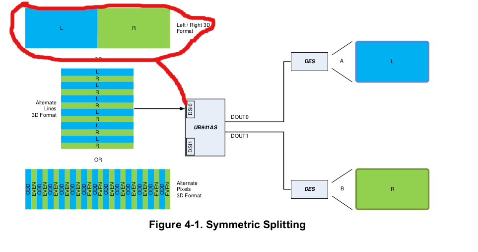
Hi Team, I am trying to enable superframe (3840x720) configuration of UB941 on Jacinto7 platform but can't see anything on the screen. Alongwith configurations of UB941, I have also configured the video port of the J7 DSS to have double H parameters. Am I missing anything? 

  • Hi Max,

    What DES are you using? If it is the 948 can you probe the OLDI lanes to ensure the video is being output properly? Is the DES locked? What script are you using?

    Regards,

    Michael W.

  • Hi,

    I have used RevB_941AS_SuperFrame_Calc.xlsm to generate commands and observing that UB948 is not responding on i2c bus after configurations are done.

  • Hi,

    Can you check the LOCK pin of the 948? also can you send me your script that you are using?

    Regards,

    Michael W.

  • I am seeing that UB941 is showing busy status on i2c bus so effectively both UBs are not invalid states.

    My script for 941 is:

    UH941AS = 0x18
    board.WriteI2C(UH941AS,0x01,0x08)

    # set split mode
    board.WriteI2C(UH941AS,0x1E,0x01)
    board.WriteI2C(UH941AS,0x5B,0x07)
    board.WriteI2C(UH941AS,0x56,0x80)
    board.WriteI2C(UH941AS, 0x4F, 0x84)
    #####
    board.WriteI2C(UH941AS,0x1E,0x02)
    board.WriteI2C(UH941AS,0x5B,0x07)
    board.WriteI2C(UH941AS,0x56,0x80)
    board.WriteI2C(UH941AS, 0x4F, 0x84)
    #####

    board.WriteI2C(UH941AS, 0x1E, 0x01)

    board.WriteI2C(UH941AS, 0x32, 0x80)
    board.WriteI2C(UH941AS, 0x33, 0x07)
    board.WriteI2C(UH941AS, 0x36, 0x00)
    board.WriteI2C(UH941AS, 0x37, 0x80)
    board.WriteI2C(UH941AS, 0x38, 0x7F)
    board.WriteI2C(UH941AS, 0x39, 0x07)
    board.WriteI2C(UH941AS, 0x3A, 0x00)
    board.WriteI2C(UH941AS, 0x3B, 0x00)
    board.WriteI2C(UH941AS, 0x3C, 0xCF)
    board.WriteI2C(UH941AS, 0x3D, 0x02)

    board.WriteI2C(UH941AS, 0x1E, 0x02)

    board.WriteI2C(UH941AS, 0x36, 0x00)
    board.WriteI2C(UH941AS, 0x37, 0x80)
    board.WriteI2C(UH941AS, 0x38, 0x7F)
    board.WriteI2C(UH941AS, 0x39, 0x02)
    board.WriteI2C(UH941AS, 0x3A, 0x00)
    board.WriteI2C(UH941AS, 0x3B, 0x00)
    board.WriteI2C(UH941AS, 0x3C, 0xDF)
    board.WriteI2C(UH941AS, 0x3D, 0x01)


    board.WriteI2C(UH941AS,0x1E,0x01)
    board.WriteI2C(UH941AS, 0x40, 0x04)

    board.WriteI2C(UH941AS, 0x41, 0x05)

    board.WriteI2C(UH941AS, 0x42, 0x1E)
    board.WriteI2C(UH941AS,0x40,0x08)

    board.WriteI2C(UH941AS,0x41,0x05)

    board.WriteI2C(UH941AS, 0x42, 0x1E)


    board.WriteI2C(UH941AS,0x01,0x00)

  • Hi,

    Can you send me a picture of your setup?

    Why are you setting the DSI settings for DSI1 if you are using superframe?

    Were you able to check the lock pins on the 948s?

    Here is a superframe script that we have tested to work that can use as reference. You will need to change TSKIP and the "START and "STOP" values though.


    UB941AS = 0x18
    UB948 = 0x58

    board.WriteI2C(UB941AS,0x01,0x02) # Reset
    time.sleep(0.1)
    board.WriteI2C(UB941AS,0x01,0x08) # Disable DSI
    board.WriteI2C(UB941AS,0x1E,0x01) # Select port 0


    board.WriteI2C(UB941AS,0x4F,0x8C) # 4 Lane Mode continuous clock

    board.WriteI2C(UB941AS,0x5B,0x07) # Splitter mode

    board.WriteI2C(UB941AS,0x40,0x04) # TSKIP_CNT
    board.WriteI2C(UB941AS,0x41,0x05) # TSKIP_CNT
    board.WriteI2C(UB941AS,0x42,0x3C) # TSKIP_CNT

    board.WriteI2C(UB941AS,0x56,0x80) # L/R Pixel Processing
    board.WriteI2C(UB941AS,0x32,0x80) # Set 2D Line Size 1920
    board.WriteI2C(UB941AS,0x33,0x07) #

    board.WriteI2C(UB941AS,0x1E,0x01) # Select port 0: 1920x720
    board.WriteI2C(UB941AS,0x36,0x00)
    board.WriteI2C(UB941AS,0x37,0x80) # X Start = 0
    board.WriteI2C(UB941AS,0x38,0x7F)
    board.WriteI2C(UB941AS,0x39,0x07) # X Stop = 1919
    board.WriteI2C(UB941AS,0x3A,0x00)
    board.WriteI2C(UB941AS,0x3B,0x00) # Y Start = 0
    board.WriteI2C(UB941AS,0x3C,0xCF)
    board.WriteI2C(UB941AS,0x3D,0x02) # Y Stop = 719

    board.WriteI2C(UB941AS,0x1E,0x02) # Select port 1: 1920x720
    board.WriteI2C(UB941AS,0x36,0x00)
    board.WriteI2C(UB941AS,0x37,0x80) # X Start = 0
    board.WriteI2C(UB941AS,0x38,0x7F)
    board.WriteI2C(UB941AS,0x39,0x07) # X Stop = 1919
    board.WriteI2C(UB941AS,0x3A,0x00)
    board.WriteI2C(UB941AS,0x3B,0x00) # Y Start = 0
    board.WriteI2C(UB941AS,0x3C,0xCF)
    board.WriteI2C(UB941AS,0x3D,0x02) # Y Stop = 719

    board.WriteI2C(UB941AS,0x01,0x00) #Release DSI

  • Also here is an app note to check out: 

  • Hi Michael, Thanks for the script. I tried it but panels remain blank. I think the issue is with the clock frequency. We are configuring UB941 to use DSI reference clock. It means that in my case it should be set to 50 * 2 = 100MHz but it seems that Jacinto7 platform got some issues as it does not work if we will change its frequency (it is ~75Mhz) Ref:

    Could we configure UB941 to use its internal reference clock? In this case do we need to double the hsync length, hfp and hbp parameters for Jacinto7 DSS?

  • Hi,

    You can use the internal refrence clock by setting the BRIDGE_CLK_MODE register to 0b'10. The internal reference clock is only for testing and debugging and not for use in final products. 

    This documents "3 Bring-up and Debug Flow" is a great step by step debug guide that you should follow.

    Regards,

    Michael W.

  • Hi Michael, I was going through snla356.pdf and made a notice of the following:

    As per my understanding DSI of Jacinto7 is producing pclk of 74250000 which means UB941 is having running  (74250000×4)÷12 = 24.75 MHz. Am I right?

    Could I manipulate DSI_PCLK_DIV_M/DSI_PCLK_DIV_N or SPLIT_CLK_CTL0_SPLIT_CLK_CTL0_P1/SPLIT_CLK_CTL1_SPLIT_CLK_CTL1_P1 registers to have the required pclk for the downstream panels (50Mhz * 2)?

    A couple of other questions to make sure that I am doing correct configurations:

    1) My output from DSI is arranged in Left/Right 3D Format Support. Do I need to set BRIDGE_CFG2->LEFT_RIGHT_3D? As it is not alternate pixel format.

    2) On reading DUAL_STS_DUAL_STS_P1, I have found that NO_DSI_CLK bit is set.

    Thanks,

  • Hi,

    Your images did not attach properly.

    "DSI of Jacinto7 is producing pclk of 74250000" what do you mean? if your PCLK for each image is 74.25 MHz then the FPD-Link rate is 74.25MHz * 35 = 2.59875 Gbps or 1299.375 MHz. 

    "1) My output from DSI is arranged in Left/Right 3D Format Support. Do I need to set BRIDGE_CFG2->LEFT_RIGHT_3D? As it is not alternate pixel format."

    I do not understand your question can you try reattaching your picture?

    2) On reading DUAL_STS_DUAL_STS_P1, I have found that NO_DSI_CLK bit is set.

    This means that there is no DSI clock on the DSI port1

    Regards,

    Michael W.

  • "1) My output from DSI is arranged in Left/Right 3D Format Support. Do I need to set BRIDGE_CFG2->LEFT_RIGHT_3D? As it is not alternate pixel format."

    Please find the image below.

    2) On reading DUAL_STS_DUAL_STS_P1, I have found that NO_DSI_CLK bit is set.

    I have manipulated the DSI M/N to have the required pclk down the line.

    Now I am seeing that port 0 (1920x720) shows some part of the frame buffer but then there is garbage data as can be seen in the below picture. Whereas 2nd panel is only showing the garbage. There is no error reported via VIDEO_3D_STS (0x58) as DSI_VC_DTYPE (0x2A) is showing 1E as per expectations.

  • Hi,

    No you should not need to set this bit.

    What are both of your display resolutions and framerates are your displays?

    can you provide me a reg dump of your 941?

    Regards,

    Michael W.

  • Hi, Please find dump in attached file.

    Resolution for both panel is: 1920x720

    Thanks

    ub941:
     0 --  0
     1 --  0
     2 --  0
     3 -- 1d
     4 -- 14
     5 -- 14
     6 --  0
     7 --  0
     8 --  0
     f -- 13
    10 --  0
    11 --  0
    12 --  0
    13 --  0
    14 --  0
    15 --  0
    20 -- 7f
    21 --  0
    22 -- ff
    23 -- 7f
    28 -- 25
    2a -- 3e
    2b --  0
    2c --  0
    2d --  0
    30 --  0
    31 -- 20
    32 --  0
    33 --  4
    34 --  0
    35 -- 20
    36 --  0
    37 --  0
    38 --  0
    3a -- 85
    3b --  c
    
    ub941 @ p0
    34 --  c
    35 --  0
    36 --  0
    37 -- 80
    38 -- 7f
    39 --  7
    3a --  0
    3b --  0
    3c -- cf
    3d --  2
    3e -- 81
    3f --  2
    5a -- f9
    5f -- 37
    64 -- 10
    65 --  0
    66 --  0
    67 --  0
    6a --  0
    6b --  0
    6c --  0
    
    ub941 @ p1
    34 --  c
    35 --  0
    36 -- 81
    37 -- 87
    38 -- ff
    39 --  e
    3a --  0
    3b --  0
    3c -- cf
    3d --  2
    3e -- 81
    3f --  2
    5a -- f9
    5f -- 37
    64 -- 10
    65 --  0
    66 --  0
    67 --  0
    6a --  0
    6b --  0
    6c --  0
    
    ub941 @ dsi0
     0 --  0
     1 --  0
     2 --  0
     3 -- 1d
     4 -- 14
     5 -- 14
     6 --  0
     7 --  0
     8 --  0
     f -- 13
    10 --  0
    11 --  0
    12 --  0
    13 --  0
    14 --  0
    15 --  0
    20 -- 7f
    21 --  0
    22 -- ff
    23 -- 7f
    28 -- 25
    2a -- 3e
    2b --  0
    2c --  0
    2d --  0
    30 --  0
    31 -- 20
    32 --  0
    33 --  4
    34 --  0
    35 -- 20
    36 --  0
    37 --  0
    38 --  0
    3a -- 86
    3b --  c
    

  • Thank you, also to confirm, the 3840x720 image is sent to DSI0 and nothing to DSI1?

  • Yes, DSI1 is completely disabled.

  • Is there any register(s) which can show the hback, hfront, hsync values reconstructed by the UB941? Moreover I am assuming that IMG_LINE_SIZE should be set to active_width not the value after active_width + hfp + hsw + hbp?

  • Hi Max,

    Your Reg map seems like it is incorrect, Register 0x00 should read the device ID and yours is reading as 0x00?

  • Please find the updated ones. DSI registers were duplicated under UB941 tag.

    Regards,

    ub941:
    01 -- 00
    02 -- 00
    03 -- 00
    04 -- 00
    05 -- 00
    06 -- 58
    09 -- 01
    0a -- 17
    0b -- 00
    0c -- 47
    0d -- 30
    0e -- 00
    0f -- 00
    10 -- 00
    11 -- 00
    12 -- 00
    13 -- bb
    14 -- 00
    16 -- fe
    17 -- 1e
    18 -- 32
    19 -- 32
    1a -- 01
    1b -- 00
    1c -- 00
    1d -- 00
    1e -- 02
    1f -- 00
    20 -- 0b
    21 -- 00
    26 -- 00
    2e -- a5
    2f -- 5a
    30 -- 00
    32 -- 80
    33 -- 07
    40 -- 04
    41 -- 3b
    42 -- 0c
    4f -- 84
    50 -- 16
    54 -- 02
    55 -- 00
    56 -- 00
    57 -- 02
    58 -- 00
    59 -- 00
    5b -- 07
    5c -- 07
    5d -- 06
    5e -- 44
    60 -- 22
    61 -- 02
    62 -- 00
    63 -- 00
    6d -- 00
    6e -- 20
    6f -- 00
    c2 -- 82
    c4 -- 28
    c6 -- 00
    c7 -- 00
    
    ub941 @ p0:
    34 -- 0c
    35 -- 00
    36 -- 00
    37 -- 80
    38 -- 7f
    39 -- 07
    3a -- 00
    3b -- 00
    3c -- cf
    3d -- 02
    3e -- 81
    3f -- 02
    5a -- f9
    5f -- 37
    64 -- 10
    65 -- 00
    66 -- 00
    67 -- 00
    6a -- 00
    6b -- 00
    6c -- 00
    
    ub941 @ p1:
    34 -- 0c
    35 -- 00
    36 -- 81
    37 -- 87
    38 -- ff
    39 -- 0e
    3a -- 00
    3b -- 00
    3c -- cf
    3d -- 02
    3e -- 81
    3f -- 02
    5a -- f9
    5f -- 37
    64 -- 10
    65 -- 00
    66 -- 00
    67 -- 00
    6a -- 00
    6b -- 00
    6c -- 00
    
    ub941 @ dsi:
    00 -- 00
    01 -- 00
    02 -- 00
    03 -- 1d
    04 -- 14
    05 -- 14
    06 -- 00
    07 -- 00
    08 -- 00
    0f -- 13
    10 -- 00
    11 -- 00
    12 -- 00
    13 -- 00
    14 -- 00
    15 -- 00
    20 -- 7f
    21 -- 00
    22 -- ff
    23 -- 7f
    28 -- 25
    2a -- 3e
    2b -- 00
    2c -- 00
    2d -- 00
    30 -- 00
    31 -- 20
    32 -- 00
    33 -- 04
    34 -- 00
    35 -- 20
    36 -- 00
    37 -- 00
    38 -- 00
    3a -- 86
    3b -- 0c
    

  • Hi,

    I think we should take a step back and try to get your like up and running one step at a time. Can you get patgen to work from the 941AS to one of the 948's with the internal clock?

    Regards,

    Michael W.

  • Hi Micheal, Patgen is working both ways. I can see pattern generated by (1) UB941 (2) UB948. Moreover UB941 works fine if it is configured for 1:1 use-case as can seen output of my test app. Something is going wrong in superframe mode.

    There are two things which are making me nervous. (1) number of lanes -- my system is using 2 (2) pixel clock -- Jacinto7 DSS/DSI is having ~75MHz. Could you think of issues due to these?

    Thanks

  • Hi Max,

    Thank you for the clarification.

    1: How many DSI lanes are you using? from your MODE_SEL setting is seems to be 4 DSI lanes but for port 1 you have it set to 2 lanes.

    2: your PCLK should be about 166MHz for the full superframe image. Why would the PCLK in the Jacinto be 75 MHz?

    Regards,

    Michael W.

  • i Michael,

    1) Panel remains blank if I will force UB941 to 4 lanes via BRIDGE_CTL so that's why it is set to 2 lanes. 

    There is UB948 down the line and as per its data sheet is is 2 lanes.

    2) PCLK: There seems to be problem in changing PCLK from DSI and there are a couple of tickets related to it: 

    Do you think the issue I am facing is because of PCLK and lanes?

    Thanks,

  • Hi Max,

    1) the BRIDGE_CTL register sets the number of DSI lanes not the number of FPD_lanes. Most systems use 4 DSI lanes. also the TX_PORT_SEL(0x1E) register selects which FPD-Link and DSI port you are writing to and reading from.

    2) The input PCLK should not be changing for the 941AS you should follow the "Power-Up and Initialization" section of the datasheet.

    Regards,

    Michael W.

  • Hi Micheal, 

    1) Bear with me. Are you saying that the lanes which are referred in the picture of UB948 datasheet are the FPD_lanes not the DSI? 

    Yes I do agree with you that BRIDGE_CTL is used to configure DSI lanes and this is what I am doing. I am seeing that panel only show contents if it is set 2 lanes.

    2) I was reviewing 10.2 Power-Up and Initialization of snls640c.pdf to match my script and realized that document is asking for Register 0x40 = 0x10 which does not make sense as it is trying to manipulate reserved bits.

    I was thinking of the output I am seeing that made some observation: (1) The lines I am seeing as garbage are very pretty much consistent and they always appear as they are. (2) These lines seems to be generated from somewhere else as I have seen the same pattern after filling framebuffer with completely a different color.  It looks very odd that panel is having some part of correct contents but suddenly it will jump to these random lines.

    Thanks for the help.

  • Hi Max,

    1) The lanes the 948 datasheet is referring to is the FPD-Link Lanes, but the BRIDGE_CTL register on the 941 controls the number of  DSI lanes.

    2) This script is required at device startup like the diagrams show. the Register 0x40 = 0x10 is correct.

    Can you provide your displays timing requirements?

    Regards,

    Michael W.