This thread has been locked.

If you have a related question, please click the "Ask a related question" button in the top right corner. The newly created question will be automatically linked to this question.

TMDS181: 0x0b register of IC is not getting changed for different resolutions

Part Number: TMDS181

Hi TI Team,

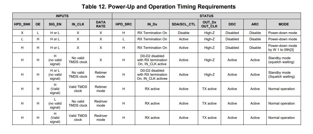
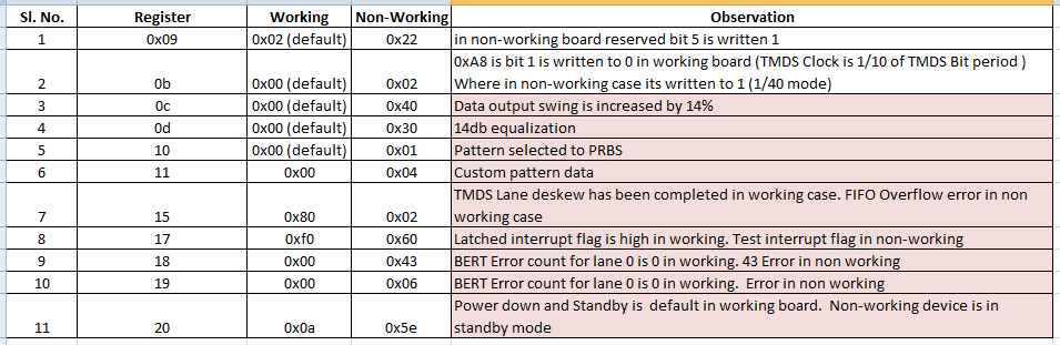
We are using TMDS181 for HDMI Sink application. Initially Pin strapping settings were given and later we have enabled I2C for debugging purpose. Currently in one board, we are able to get the input  properly for 1080p and everything looks fine. In another board we are not getting input. So we checked TMDS clock out from the IC and found that its not coming, but till IC input pin 148.5MHz clock is observed from connector. Even though the hardware configuration remains same behavior of the ICs are different. Later for debugging, we have compared register sets of both working and non-working ICs and found there are differences in few registers. 0x0b register value is 0x00 for working board and 0x02  for non-working board, which means TMDS clock is set for 1/40 of TMDS period in non-working board whereas its 1/10 in working board. To solve this, we tried writing the 0x0b register manually and found that bit 1 of 0x0b register is not getting changed. As per TI data sheet, this register is set by value of 0xA8 register value. Also it should get cleared when HPD_SINK is asserted for more than 2ms. In our case this is not happening its always set to 1. How to solve this issue..? I'll attach the compared register set values, kindly go through it and support us to solve this problem. 

Thanks & Regards,

Vyshnav Krishnan

  • Vyshnav

    Can I please take a look at your schematic? For the register 0x02 case, are you connecting to a HDMI2.0 source?

    Thanks

    David

  • Hi David,

    Yes Initially we were using HDMI2.0 source only. Currently we are able see the change in register. Also we tried by using custom EDID for 1080p resolution. At that time 0x0b is setting to 0x00 itself, but unfortunately still TMDS clock out from IC is not coming. Please find the attached image of schematics section. Currently I2C is enabled and I2C lines are connected to IC too.

    Thanks & Regards,

    Vyshnav Krishnan

  • Vyshnav

    Looking at the schematic, 

    1. Please leave TX_TERM_CTL to be NC so the TX termination is automatically selected between the HDMI1.4 and 2.0 in the pin-strap mode

    2. Please have SIG_EN pulled low to disable the signal detection circuit for now

    3. Please leave EQ_SEL to be NC to use adaptive EQ

    How do SDA_SNK and SCL_SNK being connected between the source and the sink?

    Can you also verify HPD_SNK is high?

    Where do you measure the clock output?

    Thanks
    David 

  • Hi David,

    1. I have tried by doing above settings. But when we run command still 'no link' is coming.

    2. PC is able to detect the board ( second screen is shown in PC with resolutions supported ) and TMDS clock is coming till IC input pins.

    3. HPD_SNK is high when cable is connected to HDMI port.

    4. Also  SDA_SNK and SCL_SNK from connector are connected to IC pins 39 and 38 respectively (ESD and 0ohm series resistors are also provided). At the same time these signals are being connected to FPGA pins through a level translator (5V to 1.8V). 

    I have read register settings of IC by connecting and without connecting cable. Only register 0x20 is getting changed

    Cable not connected : 0x20 value is 9e this signifies that IC is in power down state

    Cable connected : 0x20 value is 5e  this signifies that IC is in standby state

    This I have done after disabling signal detection circuit. So what and all will cause IC to go to standby mode?. Also what else can be done to solve this issue. ?

    Thanks & Regards,

    Vyshnav Krishnan

  • Vyshnav

    Below are the conditions that will place the TMDS181 into power-down or standby mode.

    Can you please remove R108 and just have the 0.22uF on the OE pin? The TMDS181 already has an internal pullup and there is no need for the external pullup resistor.

    Can you measure the 1.1V, 3.3V, and OE to make sure the OE goes high after the 1.1V and 3.3V go high? I want to make sure the TMDS181 is getting properly reset.

    Thanks

    David

  • Hi David,

    By removing pull up given for OE signal we are able to solve the issue. Currently input is detected properly. 

    This means the, power ON sequence was getting violated because of this additional pull up, because which IC was not getting reset properly.

    Correct me if am wrong.

    I would like to say thank you for your continuous support which helped to solve this issue. 

    Best Regards,

    Vyshnav Krishnan

  • Vyshnav

    Your understanding is correct. 

    Thanks

    David

  • Hi David,

    Thank you so much for your support and guidance.

    Best Regards,

    Vyshnav Krishnan