This thread has been locked.

If you have a related question, please click the "Ask a related question" button in the top right corner. The newly created question will be automatically linked to this question.

TPS65987D: Documentation for "I2Cr"

Part Number: TPS65987D
Other Parts Discussed in Thread: TIDA-050047

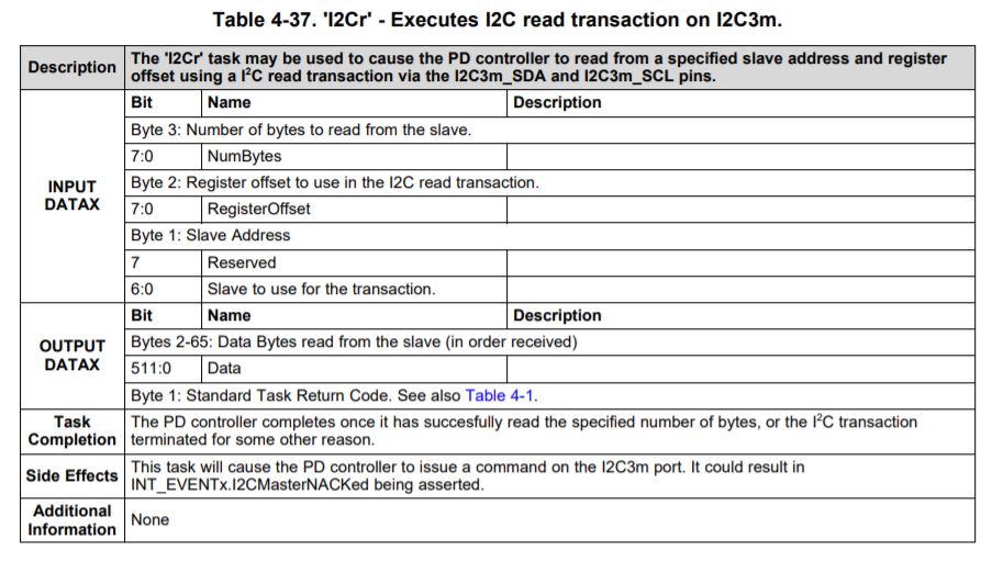
Hello , we would like to read redriver settings with "I2Cr" command , but i cant find the documentation anywhere.

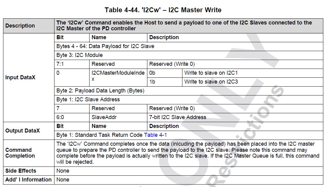
In this post I found the documentation for "I2Cw" command , could you please add the documentation part for the "I2Cr"?

Best regards,

Eriks

  • Hi Eriks,

    I can share with you the table for I2Cr, you can use this command in the same format as I2Cw. This section will be included in the next update for the document. 

    If you are looking into the using a newer battery charger, I would recommend taking a look at the TPS25750D as it will be compatible with a select few of the newer charger ICs. There is a new design as well if you'd like to take a look: TIDA-050047

    Thank you,

    Hari

  • Hello ,

    We are testing this command, but it doesn't seem to work , as i understand this command is for I2C3 master , but we are using I2C2 as slave and I2C1 as master, can we use this command to read from I2C1 master? And if no , is there a different command to do this?

    Regards,

    Eriks

  • Hi Eriks,

    This command should still be working on the other I2C port as well if it is set as Master. Could you attach your project file so that I could take a look at them?

    Did the I2Cw 4CC command work using the same format?

    Thank you,

    Hari

  • Hello,

    Here is the project file: tps65987.pjt

    The I2Cw command works as expected ,for I2Cw command I used this

    as you can see the structure of the command is different, on byte 3 you select which master to use unlike I2Cr command.

    Regards,

    Eriks

  • Hello,

    We did some more tests with "I2Cr" command.
    To start we used the "I2Cw" command to write value 0xCC to register 0xAA on retimer that has an address 0x12 . The retimer is connected to I2C1 port and this port is configured as Master.
    We sent 4CC cmd "I2Cw" on I2C2 port that is configured as Slave.

    Content of Data1 register before sending "I2Cw" 4CC

    TPS reg 0x09 (64):

    12 2 0 aa cc 0 0 0 0 0 0 0 0 0 0 0 0 0 0 0 0 0 0 0 0 0 0 0 0 0 0 0 0 0 0 0 0 0 0 0 0 0 0 0 0 0 0 0 0 0 0 0 0 0 0 0 0 0 0 0 0 0 0 0 0 0 0

    Note ,the picture is taken on I2C1 port and device ACK successfully.

    Now we tried to use the "I2Cr" command to read one value from register 0xAA

    Content of Data1 register before sending "I2Cr" 4CC

    TPS reg 0x09 (64):

    12 aa 1 0 0 0 0 0 0 0 0 0 0 0 0 0 0 0 0 0 0 0 0 0 0 0 0 0 0 0 0 0 0 0 0 0 0 0 0 0 0 0 0 0 0 0 0 0 0 0 0 0 0 0 0 0 0 0 0 0 0 0 0 0 0 0

    As you can see the "I2Cr" command does not work correctly , the first 2 bytes are correct, but then it sends the number of bytes we wish to read and then just reads a lot of junk data .
    Any help would be appreciated .

    Regards,

    Eriks

  • Hi Eriks,

    I will have to look into your data here and will provide you with some feedback later on this week.

    Thank you,

    Hari

  • Hi , Hari,

    Wanted to ask about the progress on this? Have you been able to recreate the problem ? If not , can you send the process of how you are using this "I2Cr" command?

    Regards,

    Eriks

  • Hi Eriks,

    I think that you may be running into issues in the second part of this process.

    1. You will first write the I2Cr CMD

    2. Then you will read the CMD register to verify CMD

    3. Then you will read Data1 register. 

    I have attached an example that goes through this in more detail. You will need to update your slave address and register address for your implementation. Please try that and let me know your results. Column S gives more detail to each step. 

     I2Cr_4CC_cmd_example_987.xlsx

    Thanks,

    Emma