This thread has been locked.

If you have a related question, please click the "Ask a related question" button in the top right corner. The newly created question will be automatically linked to this question.

TPS25750: Powersupply setup for system without battery

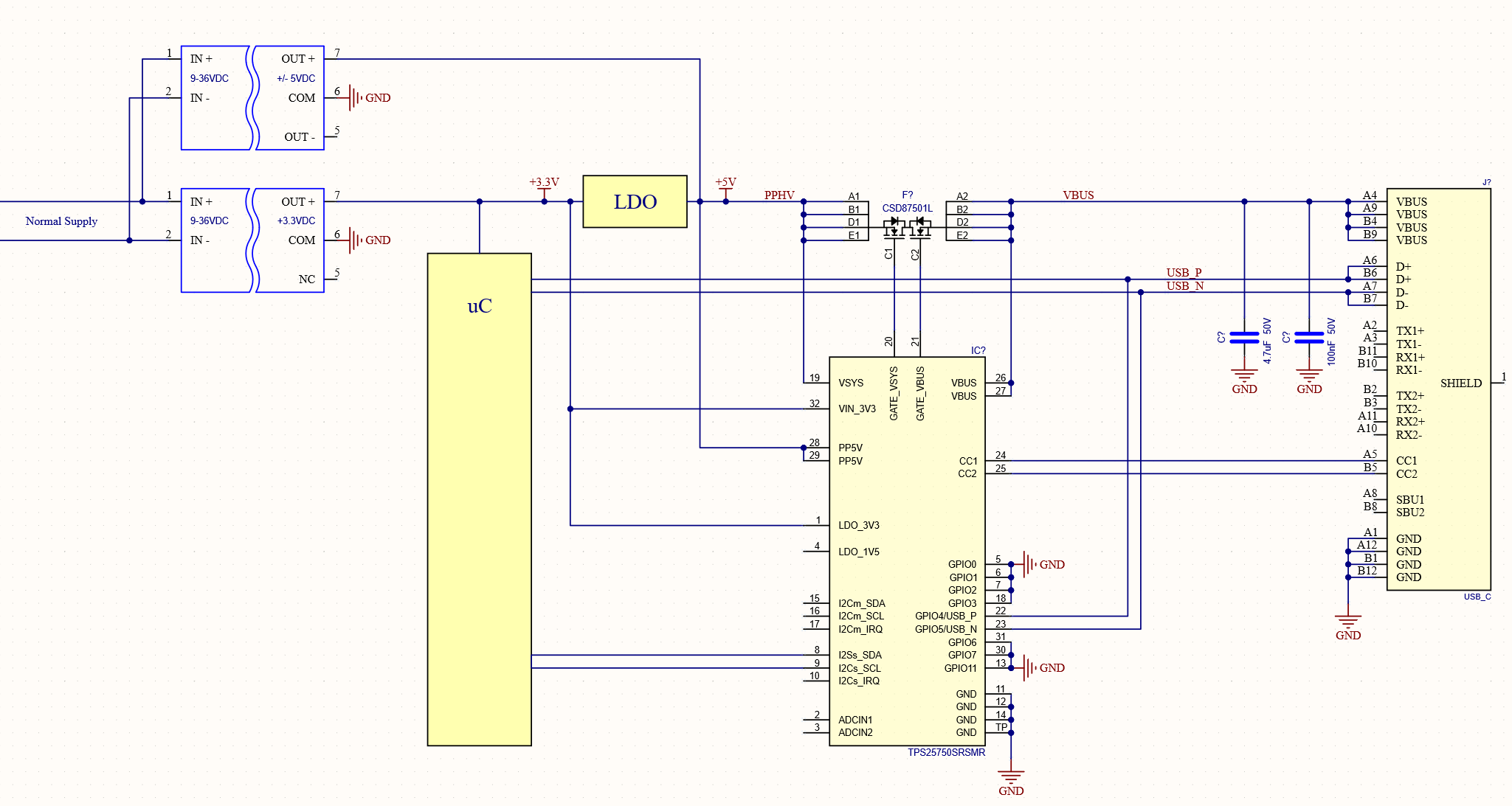
Part Number: TPS25750

Hi TI

I'm working on a design where 3.3V and 5V is generated by two DC-DC converters in paralell. Normally the product is powerd by a 24V but for servic isses I would like to power the 3.3V rail for the uC from the USB port. I will never draw more than 500mA from the USB connector and there is no battery involved in this product. When the product is powerd on the normal supply I would like to power a device connected to the USB with maximum 500mA

Since I'm using the USB-C connector I would like to protect the product against connection of non complying power supplies.

I have found that the TPS25750 should be able to solve this case. (I'm planing on using the SRSMR variant as it is the only one availeble for purchase) But I dont know if I can connect the LDO_3V3 output and the VIN_3V3 pin directly or if I need som sort of change over system in order to handle a "dead battery" condition where the normal supply is not present?

I have attached a diagram roughly outlining how I thinkt the TPS25750 should be connected for this.


  • Before I can fully answer your question, I need to confirm my understanding of your use case.

    I am assuming that during normal operation, you want to output power to the type c connection which means to use it as a DFP.

    You also want to have a mode where the Type C connector can provide power to your system as a 5V low power contract as a UFP.

    This case would require you to have a DRP port.

    Is me description of your system accurate?

  • Hello Chuck

    Thank you for your reply.
    Yes. I would like my application to work both up and down stream.
    How ever, when my design is connected upstream, I don't necessarily need to power the entire 5V rail. I basicly just need it to step down to 3.3V to power the uC. I hope that makes sence.

    Regards Rasmus

  • Your idea would work, but you do not connect LDO_3V3 to the input power supply, this is an internal LDO for the TPS25750.

    I would suggest that you consider the TPS25750D that integrates the pass fets unless you have a very specific need to use external fets that your diagram does not show.

    Here is another power tree that you can consider that matches most of what you are showing.

    The diodes for the HV path can be replaced with a switch if desired.

  • Hi Chuck

    The reason I picked the external FET is that it is the only part I can find available for purchase. But you are right I would prefer the build in version.

    Unfortunately it is not possible for me to change the layout of the power tree.

    However, I realized that I have made an error in my initial example. Under normal operation (when both the 3.3V and 5V DC-DC converter is running I will have a loop with the 5V supplying the LDO, witch in turns also supplies the 3.3V rail. I would like to avoid this. But I'm afraid this would mean that I would need a device with two separate power paths?

    Regards Rasmus

  • Rasmus,

    I also noticed that you have power connected to LDO_3V3, this is a regulator output from our device and is really intended to power something small like a boot eeprom, it can only source about 10mA.  This connection should have been to only LDO_3V3_IN.  This is the input power tree for powered accessory modes.  We have an internal diode-or circuit to be able to take power for LDO_3V3 from the VBUS when we are a sink.

    I think if you break the LDO_3V3 connection, then your power loop will resolve on the LDO 3V3 case.

    I do not see an easy way to resolve the power loop on the 5V supply if both power sources are connected at the same time.

  • Hi Chuck

    I have deleeted the connection to the internal 3.3V LDO as per you recomendation.
    I am however concerned about the potential for current to follow the red arrow when the system is running under "normal power"

    But I'm not sure TPS25750 can solve this issue. And if not, what part would you then recomend?

    Regards Rasmus

  • You would need to add a diode or circuit between PPHV and the input supply so that only one path will source current.  This is back to very similar to what I recommended in my first response.