This thread has been locked.

If you have a related question, please click the "Ask a related question" button in the top right corner. The newly created question will be automatically linked to this question.

DS90UB934-Q1: Lock and pass pins output pulse signals

Part Number: DS90UB934-Q1

Hi,

We use DS90UB933 and DS90UB934 to do a streaming media rearview mirror project.

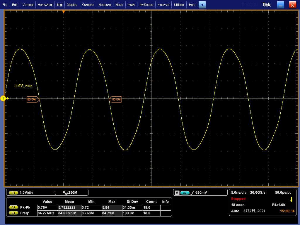
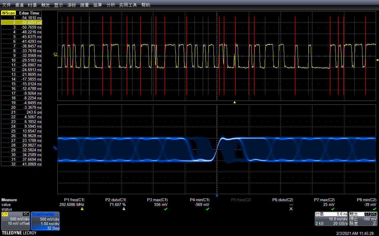
1. After the rear camera is connected, it is found that the LOCK and PASS pins of DS90UB934 output pulse signals, as shown in the figure. What is the possible cause of the failure? Where should we check?

2. The mode pin of DS90UB934 is configured with COAX RAW10, so DS90UB933 does not have this pin or register to configure COAX RAW10. How do we confirm? Is it COAX RAW10 mode just to connect DIN0 ~ DIN9 of DS90UB933 to the data line?

Tks

  • Hello,

    1. It appears that LOCK is vary intermittent and is consistently dropping.  First are you able to provide some more information regarding the system?

    • What length of cable?
    • What PCLK?
    • Can you provide status registers for both devices?

    First you should check the PCLK signal on the serializer side and verify that it is meeting the specifications in the datasheet.  Also you should verify that the channel is good and signal integrity isn't being hindered.  Are you able to probe the CMLOUT and verify that you are receiving a good signal eye from the serializer?

    2. Which mode you are running in is set on the 934 side, on the 933 side you need to verify that the timing meets the recommendations in the datasheet. Also make sure that the PCLK signal meets our specs as well.

    Regards,

    Nick

  • Hello,

    Thank you for your reply!

    1、The  length of the cable is about 1m;

    2、PCLK is provided by the external 42MHz crystal oscillator of 933,933‘s GPIO2 was connected to ISP's clockin;

    3、The Register of 933 and 934 are not configured, and the default value is used;

    4、The waveforms of CMLOUT and 933-PCLK are shown in the figure;

    5、Please confirm the schematic diagram of 933 and 934

    LLAM.pdfYT-SQ.pdf

  • Hello,

    Thank you for the data, this is helpful to understand your system.  I have questions regarding the schematic below.

    1. In your point 2 you mention that you have a 42MHz crystal feeding the 933 GPO3 in external mode, which lines up with your PCLK being 84MHz.  This meets the requirement that the PCLK frequency divided by the external clock frequency be equal to 2, but when I look at the schematic it says that there is a 48MHz crystal attached to GPO3.
    2. Another thing that concerns me is that on the 933 it appears to be set up for single ended mode which matches your 10-bit coax mode, however on the 934 side it appears that RIN is set for a differential setup.

    Is there a reason for this discrepancy?  They should be set in the same way on both the Serializer and Deserializer.

    Regards,

    Nick

  • Hi Nicholas

    Thank you for your patience!

    First of all, the unstable state of lock pin is due to ED200. I mistakenly used 20pF ESD diode. Just remove ED200.

    1. The 48MHz crystal is shown on the schematic diagram, and the 42MHz crystal is actually used;

    2. I don't quite understand what you mean. For the mode pin of 934, I use 10K pull-up, that is, the 10-bit coax mode is configured, and the 934‘s input circuit is single ended to differential. What's the problem?

    Thanks

  • Hello,

    I apologize, I took another look at the schematic and you are correct.  I skipped over the portion showing where the 934 connects using the single ended configuration.  No problem here to worry about.

    Regards,

    Nick