This thread has been locked.

If you have a related question, please click the "Ask a related question" button in the top right corner. The newly created question will be automatically linked to this question.

DP83848J: Ethernet connection breaks - layout issues?

Part Number: DP83848J
Other Parts Discussed in Thread: AM3352,

Hello,

we use AM3352 and DP83848JSQ/NOPB for a Ethernet service interface.

We see here Ethernet connection breaks once in a while:

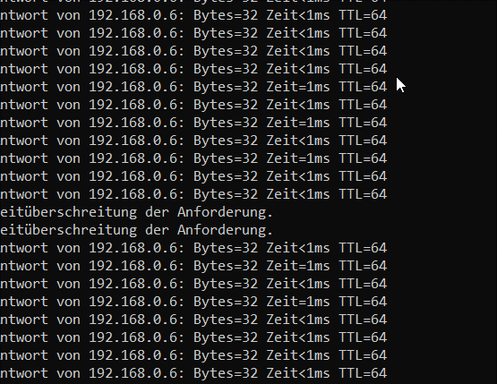
Either the ping and establishing a connection does not work or everything works and suddenly it breaks.

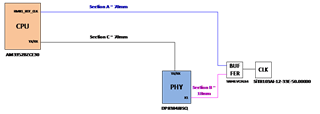
we had some EMC issues during development and had some workarounds on REF:CLK for ETH PHY. Also the clock source is in quite a distance to the Sitara. We also know that the solution with SN74LVC2G14DCK buffer is not optimal. One workaround was to increase C517 to 33pF to reduce the delay to Sitara.

With that we reduced the delay between U500 Pin 28 (DP83848JSQ/NOPB) and U100, Pin K18 (AM3352BZCE30) from 2,65ns to ~ 2ns.

PHY marking:

2021:
88A80R63
83848JSQ

2016:
49ANJKG3
83848JSQ

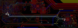
Is there anything else beside of the delay what may play a role here? Or is it just necessary to hold the delay under 2ns? please find the schematic and layout attached.

looking forward to your answer.

2870.Mainboard_CPU_ETH_PHY.pdf

Regards,

Alen

  • Hello Alen,

    I will need to talk to the team about this. I expect a response by end of Friday.

    Sincerely,

    Gerome

  • Hello Alen,

    Also to add, the attached file in your initial inquiry is only the schematic, not the layout.

    Sincerely,

    Gerome

  • Hello,

    I would like to narrow down where in the signal chain you are losing the signal, thereby causing a PING loss. At the same time PING is getting broken, are you also seeing the link drop between the PHY and its link partner? Also what is the link partner for this application and its associated MAC?

    I also see that you are using the RMII clock as the XI input to the PHY. As this signal is associated with the RMII data signals, is this trace length matched to the data (RX and TX) lines?

    Sincerely,

    Gerome

  • Hi Gerome,

    thank you for looking into this.

    I would like to narrow down where in the signal chain you are losing the signal, thereby causing a PING loss.
    At the same time PING is getting broken, are you also seeing the link drop between the PHY and its link partner? Also what is the link partner for this application and its associated MAC?

    I am not sure, if I’ve understood the term “link partner”. We have here Linux running on a custom AM3352 Board and the Ethernet interface here is only used due to service purpose.
    E.g. the technician can connect to device through the Ethernet interface with his laptop and check calibration parameters, download logs, and so on. In the production the Ethernet interface is only checked if PING is available. 
    So the Link Partner here would be PC or Laptop and normally the Command-Line-Interpreter (CMD) in windows have been used.
    In my case the MAC address of my laptop is:

    I also see that you are using the RMII clock as the XI input to the PHY. As this signal is associated with the RMII data signals, is this trace length matched to the data (RX and TX) lines?


    If the X1 signal must be matched to the RX/TX Lines, the answer is no. Does it mean, that Sections B and C must be matched?

    Addendum:

  • Hi Alen,

    A few questions:

    - What is the jitter on your output?

    - Is the buffer you are using suitable for 50MHz operation?

    - Both the CPU and PHY are being sourced by same clock, so why is there a 2ns delay? A 60mm delta shouldn't be causing that much of a delay. Can I see scope capture of the signal at both points? I'm interested in the rise and fall times.

    Sincerely,

    Gerome

  • Hi Gerome,

    hopefully the information for the first two questions and for the 4th should be provided tomorrow. Unfortunately, we have only one Active Probe (1pF Load Capacitance, 1GHz, 350ps rise time) but we can perform delay measurements with passive probes to find relative delay between these two sections.  

    Regarding the delay of 2ns, could you please compare the pin capacitance for the PHY and Sitara?
    According to the PHYs datasheet the Cin1 is specified as 5pF. However in the IBIS model the C_comp for the osc25x1 is given as 1pF. 
    For the Sitara the IBIS model specifies for the RMII1_REF_CLK the Selector_10 (BC1833DV40DCPBFBP18LL_SSDHV). This gives
    Cref =  15pF
    C_comp         2.233931p    2.204415p    2.290246p.

    If there is a difference in load capacitance for these two part (PHY and Sitara), there should be also difference in rise time and/or delay. Is this correct? 
           

    Additionally, let us assume FR4 and Er=4.0.The wave velocity is around 0,015cm/ps. For 6cm the difference in delay is around 0,4ns.

    As it was mentioned earlier, the LVC buffer is not the best option for clock buffering. Absolutely  agree with you. The issue can be solved if the load capacitance for section B, C517 will be increased. However we would like to understand what went wrong after 5 years and around 1000 pcs. of produced boards. 


    Regards

    Josko 

  • Hi Josko,

    To add on to your scope grabs, if possible, could you grab those captures in reference to some data transmission on the RMII line? While it is very important to know the relative delay between the clock signal at both points, I also would like to see these signals relative to the data line to ensure that the data is getting clocked in the correct manner.

    Regarding comparing load capacitances between the PHY and Sitara, that is rather difficult. There is a separate team handling the Sitara product line. I would encourage you to post a separate, but connected thread to them with their device being the main product in question (as opposed to the DP83848J). 

    Sincerely,

    Gerome

  • Hi Josko,

    Thank you for sending the scope captures. Unfortunately, I think to move forward, I would need a scope capture that has the clock signal of the PHY and MAC as well as the data in a single shot as I need to be able to see where each signal is relative to another. With the screenshots I got, I am only able to determine single signal characteristics (voltage, frequency, rise/fall times), but to investigate further, I need those signals in a single screenshot.

    Sincerely,

    Gerome