This thread has been locked.

If you have a related question, please click the "Ask a related question" button in the top right corner. The newly created question will be automatically linked to this question.

DS90UB960-Q1: Monitoring LOCK

Part Number: DS90UB960-Q1

Hi Team,

I am trying to understanding the best way to monitor LOCK for the 960. Can you please help with the questions below?

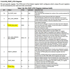
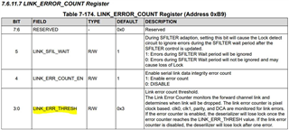
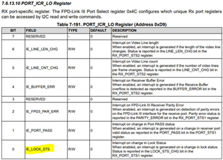
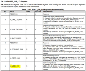
  1. Below are the registers and pins I have identified for the 960 to look for LOCK/loss of LOCK. Are there any others I have missed?
  2. Is there any way to latch a register or bit if loss of LOCK occurs?
  3. Is there any way to configure an interrupt to the SoC if loss of LOCK occurs? This looks possible with the GPIOs from the 960, but I am not totally clear on it

960


No physical pin indicates LOCK

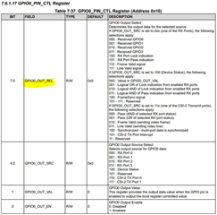
GPIOx_PIN_CTL Register (0x10 - 0x17)

Thank you,

Jared

  • Hi Jared,

    Thank you for your question. I will look into this and provide a response within 1 or 2 days.

    Best,

    Justin Phan

  • Hi Jared,

    There are no dedicated registers that only latch when a loss of LOCK occurs. Instead, you can monitor the LOCK_STS_CHG bit (0x4D[4]) for interrupts when a change in LOCK status has occurred. This bit is 0 by default. After a change occurs in the LOCK status, then it sets to 1 and clears when read. The LOCK_STS bit (0x4D[0]) can be read during the interrupt event to determine the current state of the LOCK. 

    Best,

    Justin Phan

  • Hi Justin,

    Is there a way to create an interrupt to the SoC when loss of lock happens? For the 960, there does not appear to be a dedicated LOCK pin, so is the best method to configure one of the GPIOs to represent the current status of LOCK?

    Thank you,

    Jared

  • Hi Jared,

    You can refer to register 0xD9 (PORT_ICR_LO) to configure interrupt generation for changes in LOCK status and register 0x4D to read/clear the interrupt conditions and find the current LOCK status. There is also an interrupt output pin (INTB pin 6) which can be configured to generate interrupts through register 0x23 (INTERRUPT_CTL_REGISTER).

    It is also possible to configure GPIO for LOCK, or send interrupts. Each GPIO pin can be programmed to output data. You can look at GPIO1_PIN_CTL (for example) and set GPIO1_OUT_SEL to 100 (RX Port Lock Indication). And then select the GPIO1 Output Source Select and Enable output. In output mode, the Lock status can be read through an oscilloscope.

    Best,

    Justin Phan

  • Hi Justin, 

    Can you please confirm the following sequences are correct for configuring an interrupt on loss of LOCK?

    INTB -> set bits 0,1,2,3, and 7 of register 0x23 -> If loss of LOCK occurs, INTB pin will be pulled low -> configure 0x4C to determine which port you want to look at -> read 0x4D to determine a LOCK status change (bit 4) and/or current status of LOCK (bit 0)

    GPIO -> there are enough GPIOs to configure a GPIO to align with each Rx port. For example, GPIO1 in register GPIO1_PIN_CTL (0x11) can be configured to flag based upon the status of LOCK (bits 7:5 = 100)

    Thank you,

    Jared

  • Hi Jared,

    You can refer to Section 7.5.9.2 FPD-Link III Receive Port Interrupts in the UB960 datasheet for the correct sequence to enable/clear interrupts from the Receive ports. 

    For the GPIOs, you can refer to Table 7-37 to Table 7-44 in the UB960 datasheet to configure each of the 8 available GPIO. Since there are 4 Rx ports and 8 GPIO pins, there are more than enough GPIOs to cover each port. You can configure GPIO for LOCK by setting (bits 7:5 = 100) and selecting the corresponding Rx source in (bits 4:2). 

    Best,

    Justin Phan