This thread has been locked.

If you have a related question, please click the "Ask a related question" button in the top right corner. The newly created question will be automatically linked to this question.

DP83867IS: Receive OK - No Transmit

Part Number: DP83867IS
Other Parts Discussed in Thread: MIO

Hello,

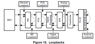
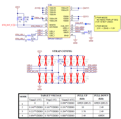
I'm having a problem; however, I'm not sure if Strap Config is not right or VDDIO has wrong voltage value. My SW guy tested with simple "ping" from another PC, he could see the receive data, but cannot transmit "ack" back. The TX side didn't work. He also tested the "Loopback" from MAC to MII (1st level) as shown below and did not see anything because of the TX side did not send anything.

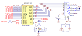
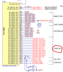
Here is the connection from my schematic. This PHY device is connected directly to Xilinx Zynq. Both devices used 3.3V for IO to eliminate extra voltage shifter device.

What did I do wrong here in HW connection? Your help is appreciated much.

Thank you.

  • Hi Long,

    Let me take a look at the schematic, and I will get back to you with comments on Monday.

    Regards,

    Adrian Kam

  • Hi Long,

    1. Do you see any signals/data on the RX/TX pins? Or is nothing being seen on the scope on those pins?
    2. Can you check the register data, specifically register 0x006E, to make sure that RGMII is enabled and that SGMII is disabled?
    3. If you do see signals on the RX/TX pins, can you try experimenting with different RX/TX clock skew settings?

    Regards,

    Adrian Kam

  • Hi Andrian,

    I see 125MHz on RX CLK with amplitude ~2.5V. For The TX CLK, it's 125MHz with amplitude ~3.3V. I changed VDDIO from 3.3V to 2.5V, and I did same voltage for Zynq MIO bank to 2.5V.

    I still see RX_CLK, RX_CTL, and RX_Dx toggling all the time.

    On the TX side, I see TX_CLK toggling @ 125MHz. The TX_CTL and TX_Dx are flat. No toggling. From my schematic, what is the normal setting for STRAP CONFIG?

    I'm using the package DP83867CRRGZT, so TX_CLK is actually GTX_CLK (pin 29).

    Thank you.

  • Hi Long,

    If you are not seeing any signals on the TX pins of the PHY, that indicates that the MAC device is not sending anything out onto those lines. Can you check if your MAC device is functioning properly?

    Regards,

    Adrian Kam

  • At power on, the RX_CLK is 125-MHz by default. The TX_CLK is not running. When the Registers are setup via MDC-MDIO, I can see the TX_CLK running continuously at 125-MHz. However, I cannot see TX_CTL and TX_Dx toggle when sending "ping IPADDR" command.

  • Hi Long,

    If you cannot see a signal on the TX_Dx pins when you are sending packets, like your "ping IPADDR" command, then it seems like your MAC device is not properly sending the signal out to the PHY. Can you check to see if you MAC device is functioning properly?

    Regards,

    Adrian Kam

  • Hi Adrian,

    Do you have any the following documents or links?

    1. Ref Design for this device
    2. Program User Guide
    3. Documentations for 4-level Mode, with detail definition. I find datasheet generally put Mode-1 to Mode-4 with different resistor setting. But did not explain what each mode does. Example, RX_Dx Strap Mode. You have a clear definition for Registers, but not mode Strap Config Modes.

    Thank you.

  • Hi Long,

    1. Here is a link to one of TI's reference design that uses the DP83867: https://www.ti.com/tool/TIDA-010010#technicaldocuments'
    2. All documents we have regarding the DP83867 is on the product page. If you are referring to the user guide for the DP83867 EVM, it can be found here: https://www.ti.com/tool/DP83867ERGZ-R-EVM.
    3. Each mode sets the strap bits to the values specified in Table 6 of the datasheet. For example, RX_D2, when strapped to mode 3, sets PHY_ADD3 = 1 and PHY_ADD2 = 0. PHY_ADD3 and PHY_ADD2 are the first two bits of the PHY address. Details on the strap bit configurations can be found in Table 7, 8, 9 of the datasheet.

    Regards,

    Adrian Kam

  • Hi Adrian,

    After troubleshooting, I found that RJ-45 had reversed differential-pair order. When I reverse the RJ-45 connector, seems like it passed external loopback test with external loopback cable. But when I plug the cable to network, I don't see LED lid up from the network router, which means no traffics on RX/TX at RJ-45. It seems to be twisted pairs.

    So my question is "does differential-pair order matter"? For example, the order as "TDA-TDB-TDC-TDD" or "TDD-TDB-TDC-TDA" connect to RJ-45? If you look at my attached schematic from previous posts, you might see connection problem between PHY and RJ-45.

    By the way, the datasheet on Page 117 for this device shown an external magnetic. Do I need an external magnetic if I use integrated magnetic RJ-45 connector?

  • Hi Long,

    1. Differential-pair order should not matter. The PHY is able to detect when the polarity of the MDI pins is reversed or normal. You can read the polarity status by reading register 0x0011. If the polarity is reversed, you can manually adjust for it by enabling mirror mode through strap or by writing to register 0x0031. In addition, the PHY has a feature called auto-MDIX where it can detect if the MDI polarity is reversed and automatically reverse the channels. Can you try enabling automatic crossover (bit[6:5] in register 0x0010) and see if that solves your issue?
    2. External magnetics are not needed if you use an RJ-45 connector with integrated magnetics. Just keep in mind that the magnetics in the RJ-45 connector should match the figure in section 9.2.1.1 of the datasheet. In particular, the center taps on the left should NOT be shorted.

    Regards,

    Adrian Kam

  • Hi Adrian,

    I have PHY ADDR issue. RX_D0 and RX_D2 Strap Config are for PHY ADDR. When both OPEN, no external resistors, the ADDR should be 0x0, but when I read the register, the PHY ADDR is 0xD. Then I install strap resistors for RX_D0 and RX_D2 as Mode 2 & 3 respectively per example on Page 54 of datasheet. Then the new PHY ADDR should be 0x9, but it's read 0xE. What did I do wrong here?

    Another problem when I made actual measurement at RX_D0 and RX_D2 strap resistors (voltage divider), I see 2 different voltages in the below scenario:

    1. Disconnect network cable -> Power On -> No code running -> Vstrap (voltage divider) is 0.024V
    2. Then plug in network cable -> Vstrap is 2.4V (still no code running)
    3. VDDIO is set at 3.3V, the Vstrap (voltage divider) isn't in range as shown in Table 4, Page 47 per datasheet. I used exactly same values in Table.

    Is this why the PHY ADDR isn't read correctly? What did I do wrong?

    Thank you.

  • Hi Long,

    The voltage on the strap pins are only read during the power up phase of the PHY, which means after power up is complete the voltage on that pin should not affect any configurations. If the PHY ADDR you are reading is different compared to the strap registers, it is possible that there is some voltage on the RX_D0 and RX_D2 line during the power up phase that is not from the strap circuitry. Can you check if that is the case? Is there some voltage coming from the MAC?

    Regards,

    Adrian Kam