This thread has been locked.

If you have a related question, please click the "Ask a related question" button in the top right corner. The newly created question will be automatically linked to this question.

TPS65988: Help us to select optimal battery charger/monitor and PD controller parts for our use-case

Part Number: TPS65988
Other Parts Discussed in Thread: TPS25750, BQ25792

Hello, guys!

We are currently designing a device that will be powered with three 18650 cells connected in series - 3S1P configuration.

Consequently, a PD controller will be needed to boost VBUS voltage above 5V if we want to charge three 18650 cells.  On the other side, we want to use the same USB-C connector (VBUS, D+/D- lines) for connecting our Host MCU (supports only USB2.0) with the PC. 

When the PD charger is connected to the USB-C port and when we boost VBUS to ~12V in order to start the battery charging process, this would immediately burn our Host MCU that can tolerate up to 5.8V on its VBUS input. Is there any possibility to avoid this scenario?

Do we always start with +5V on VBUS pins even if we connect the PD charger to the USB-C port and then it is the PD controller that requires boosted voltage on VBUS during the negotiation phase (over the CC interface)?

Would it be possible for PD controller to inform the Host to disconnect itself from the VBUS rail (e.g. with the help of a load switch) before PD charger starts with the charging phase?

I came across your webinar about USB-C and Power delivery (link). There is a reference design I found that contains all the pieces we need in our system:

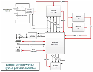
However, this seems to be slightly overcomplicated for our use case. We would need a simpler PD controller. Moreover, this reference design is from October 2017.

Would you be so kind to recommend us the key parts in reference design (PD controller, charger, Gas Gauge...) that are more up-to-date?

Thank you very much for your time and efforts.

Sincerely,

Bojan.

  • Hi Bojan,

    Please take a look at the following reference design: https://www.ti.com/tool/USB-PD-CHG-EVM-01 . I think this could be a good solution to what you are looking for. The TPS25750 is an easy to use device with a simpler structure over the TPS65988. 

    Thanks,

    Emma

  • Hello, .

    Thanks for the suggestion.

    Even with this TPS25750 PD controller, we will be in trouble when we boost VBUS to 15V during the charging phase because our Host Micro-controller will have its VBUS pin connected to the VBUS of the USB-C connector. 15V on VBUS will burn our Host MCU. Is this correct or I am missing something? Is there any workaround to avoid burning our Host MCU during the charging phase?

    One more thing... we would like to know the current state/capacity of the battery so that we can alarm the user that the battery is low, for example. Do we have the ability to monitor the battery voltage with the BQ25792 charger you suggested or a separate Gas Gauge&Cell balancer will be needed?

    Thanks in advance.

    Sincerely,

    Bojan.

  • Hi Bojan,

    Do you have to have your Host MCU attached to VBUS? If the host MCU cannot handle 15V then it will be burned when VBUS goes to 15V. You could consider placing the Host MCU on a different rail in order to ensure it will not be burned.

    I am a Type-C expert, so if you submit another question under the BQ25792 part title, the battery charging team can provide you more detailed information on your battery status question. 

    Thanks!

    Emma 

  • Hi, .

    We need a Host MCU connected to VBUS. How about having some +5V LDO voltage regulator between the VBUS of the USB-C connector and the VBUS pin of our Host MCU? For example, TPS7B81. This LDO would ensure we have stable 5V for Host MCU for a wide range of VBUS voltages on USB-C connector (from 5V to 20V). Does that seem like a good workaround to you?

    Other than that, concerning PD controller and negotiation between PD controller and PD charger... What happens when we connect the PD charger to a USB-C connector, do we always start with 5V on VBUS and boost it after the negotiation phase? Would it be possible for the PD controller to inform the Host MCU that the voltage on USB-C VBUS will be boosted (so that the Host MCU could disconnect from the VBUS before that)?

    Thanks once again for all your efforts.

    Sincerely,

    Bojan.

  • Hi Bojan,

    Would the LDO supply enough current to support an MCU? My only other concern with this solution would be heat dissipation caused by an LDO. You could also look at a buck.

    Thanks,

    Emma