


Part Number: DP83848-EP
Hi team,
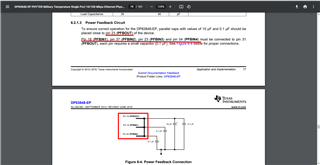
How should the highlighted pin numbering in section 6.2.1.3 of the datasheet of the DP83848-EP be interpreted?
Part Number: DP83848-EP
Hi team,
How should the highlighted pin numbering in section 6.2.1.3 of the datasheet of the DP83848-EP be interpreted?
