This thread has been locked.

If you have a related question, please click the "Ask a related question" button in the top right corner. The newly created question will be automatically linked to this question.

TUSB564: Custom Design: Valid USB 3.x, No DisplayPort

Part Number: TUSB564
Other Parts Discussed in Thread: TPS25750, TUSB321, TPS65988, TUSB422

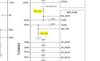
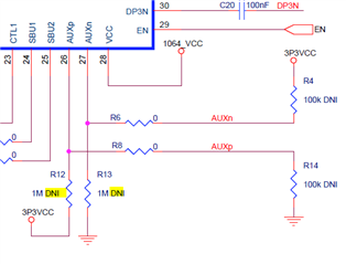
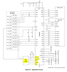
I'm working with a custom PCB design built around the TUSB564. The USB (both 2.0 and SuperSpeed) work exactly as expected, but the DisplayPort sink is never detected by my host system (Windows). My schematic is virtually identical to the suggested design in the datasheet [link] as well as the reference design [link]. I've confirmed that HPD is going high when the DisplayPort sink is connected, but am otherwise not seeing any evidence of communication (which leads me to believe there's an error in the AUX lines). At this point, I'm at my wits end trying to figure out what else might be wrong. Any suggestions the community may have would be most appreciated. Thanks!!!

My Design: 8547.USB HUB.pdf

Note that, while this design outputs data over 30-pin and 40-pin Molex connectors, I have a Test Board that converts them into standard DisplayPort and USB-C jacks. In this incarnation, the DisplayPort goes directly to a computer monitor (via a known-good DP cable).

  • Hi,

    It looks like you are missing the necessary AUX_P/AUX_N 1M pull-ups/pull-downs to bias the internal TUSB564 SBU-AUX mux. This will lead to no AUX communication and no connection to the DP link. You can try adding external leaded resistors to provide the correct biasing, this may resolve your issue. Please let me know if I missed something in your schematic. 

    Also I recommend TX1/2 should be AC coupled with 220nF and RX1/2 should be AC coupled with 330 nF. 

  • Thank you! I had found the 1M-ohm resistors and was afraid that might be the issue. For whatever reason they're flagged as DNI in the reference schematic... hence my initial exclusion.

    I'm trying to add external resistors for test, but can only connect them after the AC coupled capacitors... so I suspect that to be the reason it's still not working. Is that a rational explanation?

    In the meantime, I've updated my schematic as per your recommendations (thanks again!)... so if worst comes to worst, I'll just refab and hope for the best.

  • Out of curiosity, why are these 1M resistors DNI on the reference schematic? How is it possible that that system works?

  • Hi Kyle,

    I agree this is most likely the case. This resistor are left DNI because the EVM goes to a DP receptacle where the AUX biasing voltage is already provided from DP sink. When "embedding" TUSB564 these resistors should be included. 

  • I've managed install 1M pullup/pulldown resistors on my AUX_P/AUX_N lines (between the IC and the AC-coupled capacitors), but my host PC still doesn't recognize any DisplayPort devices. I've also tried 100k resistors on opposing lines (as per the reference diagram) but that didn't make any difference either. At this point, I'm at a complete loss as to why my SuperSpeed USB data is working perfectly, but I can't see my DisplayPort device.

    Molex-to-DisplayPort: Test-Board.pdf (far-left circuit)

    I've attached my "Test Board" circuit, which converts the 30-pin Molex connector to a standard DisplayPort socket... just in case there's an error there. Beyond that, I have no idea what might be wrong. Any and all suggestions would be most appreciated... thank you!!!

  • Hi Kyle,

    I took another look at your schematic. Since you are using TUSB321I which is a CC controller your board will not be able to negotiate DisplayPort atl mode. TUSB321I can only "negotiate for USB only. You can refer to the FAQ below detailing the differences between the two types of devices. I would recommend looking into the TPS25750 Which can work for this application.

    https://e2e.ti.com/support/interface/f/interface-forum/843553/faq-when-do-i-select-a-pd-controller-or-cc-controller-for-usb-type-c-applications 

  • Thanks Malik,

    I'm afraid I'm still struggling a bit to fully comprehend the necessary data path and, therefore, have a couple of questions:

    1. The part you recommended (TPS25750) explicitly states that Alt-Mode isn't supported:


      Is it possible that was a typo?

    2. The TUSB564 datasheet indicates that the PD Controller is only used for: FLIP, CTR0, CTL1, HPDIN, and EN.


      Since I'm manually setting all necessary signals, I don't understand what additional capability is required out of the PD Controller (as oppose the CC controller).

    3. The TUSB564 has dedicated pins (CTR0 and CTR1) to manage its various modes (when not operating in I2C, which I've disabled):


      This seems to imply that the TUSB564 is fully capable of establishing a DisplayPort connection on it's own... hence my design built without a dedicated PD controller.

    4. I've found references elsewhere on this forum that the TUSB564 can indeed support DisplayPort when in GPIO mode (rather than I2C). For example, the following is very similar to my use-case:

      https://e2e.ti.com/support/interface/f/interface-forum/689973/tusb564-tusb564-displayport-can-not-work-correctly

      The issue there was that the developer was using a prototype IC, which is not applicable to my use-case. It does seem that he was able to propagate DisplayPort albeit via hard-wired SBU/AUX connections.

    Bottom line, my use-case is extremely fixed: always requiring One Port USB 3.1 + 2 Lanes DP. My PCB is also extremely space-limited, so I selected the TUSB564 explicitly to bypass the need for external controllers. I originally didn't even include the TUSB321, but added it as an after-thought to support cable-orientation-flipping (otherwise I was just going to accept that the cable would only function in one orientation).

  • Hi Kyle,

    Let me fill in some details here then answer your questions. When implementing Type-C the the initial connection for USB and other alternate modes are dictated by the CC/PD controller over the CC lines. CC controllers control where and when Vbus is sourced to the sink. PD controller do the same but also use PD messaging to start negotiation of  different alternate modes. This is required for both source and sink to enable their internal USB-C muxes to the correct modes to establish the DP link. One key point to understand is that TUSB564 is only a redriver mux and is used to connect the physical path of DP source to the DP Sink and improve signal integrity in the link. It is not directly involved in the connection discovery process that occurs on the CC line through PD messaging. As your design exists today, a connected DP source has no way of knowing your design supports DP alt mode since a CC controller is being used therefore the source assumes this is a USB only application (defined by USB-C spec). 

    1. My apologies this was a typo, please refer to TPS65988 to get in the right ball park. I do not fully support the PD controller portfolio, mainly USB/USB-C redrivers. for further question I recommend posting a new question using the TPS65988 PN.

    2. You would want the PD controller GPIO to the configuration pins of the TUSB564 to responded to changes in the USB-C connection automatically. One example here is when the connector is flipped, the PD controller would inform TUSB564 through a GPIO signal.

    3. As I mentioned previously TUSB564 is a redriver mux and the table you mentioned is informing the user of the different mux modes based on GPIO signal input. This inform you that the physical path for the DP signals (including AUX)  is established but does not handle the initial PD negotiation which is necessary to start the DP connection.

    4. TUSB564 can support DP alt mode in GPIO mode either through  PD controller GPIO control or manual control. However the initial PD messaging to inform the DP source that there is DP sink attached is still required. Manual (human) control is not recommend since at the initial connection (after PD messaging is successful) TUSB564 may be in the a incorrect mode. For you fixed application you may be able to get away with fixed GPIO signals.

    In the post you refence it is not mentioned but a PD controller is used. Even if the ability to mux, redriver and sink DP video is present in the Sink device the source must know, upon connection, if this mode is supported which is negotiated through PD messaging. That being said you could used a standalone PD controller or TUSB422 (PD controller PHY) with an external MCU to implement this PD messaging to enable DP alt mode.

  • Malik,

      Thank you for the thorough response! I'm clearly new to the world of USB-C Alt-Mode, so I really appreciate the education. We're going to take your comments into advisement and redesign our system accordingly.

  • Hi Kyle,

    No problem. Feel free to post general Type-C spec questions too, our team can help answer. (You can use TUSB564 as the PN)