Because of the holidays, TI E2E™ design support forum responses will be delayed from Dec. 25 through Jan. 2. Thank you for your patience.

This thread has been locked.

If you have a related question, please click the "Ask a related question" button in the top right corner. The newly created question will be automatically linked to this question.

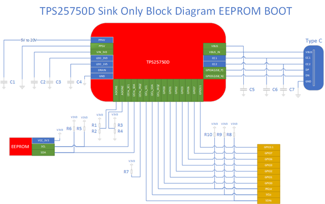
[FAQ] TPS25750: How do I create a Sink-Only USB-C PD port to replace a legacy Barrel Jack Connector?

Part Number: TPS25750

I want to replace a Barrel Jack connector with a USB-C PD port. The USB-C PD port only needs to Sink power. How can I optimize the schematic with the TPS25750 to achieve this functionality?

  • Below is a block diagram with the minimum set passive components to implement a UFP (Sink) using the TPS25750D

    Passive Components
    Name Value
    C1 47uF, 25V
    C2 10uF, 6.3V
    C3 10uF, 6.3V
    C4 10uF, 4V
    C5 4.7uF, 25V
    C6 330pf, 25V
    C7 330pf, 25V
    R1 DNI
    R2 0 Ω
    R3 DNI
    R4 0 Ω
    R5 2.2 kΩ
    R6 2.2 kΩ
    R7 10 kΩ
    R8 2.2 kΩ
    R9 2.2 kΩ
    R10 10 kΩ

    Design Consideration Checklist:

    1. In order to program you EERPOM easily during your system bring up, We recommend that you add a 3 pin header that connects to the three following pins of the TPS25750D:  I2Cm_SCL, I2Cm_SDA, and GND.
      1. When selecting this header, also consider what EEPROM programming solution you plan to implement.  There are many I2C eeprom programmers on the market.
    2. Connect PP5V to GND as shown in the diagram.  This path is not used
    3. Connected VBUS to VBUS_IN
    4. Make sure that you size C1 to C7 according to the Recommended Capacitance Table on page 9 (Section 7.4) of the TPS25750 USB Type-C and USB PD Controller with Integrated Power Switches datasheet (Rev. A)
    5. The EEPROM, R6, and R5 must all be powered by LDO_3V3 so that the EEPROM has power when the TPS25750D attempts to read from it
    6. Size all resistors according to your I2C system speed and system needs.  The datasheet values are a good approximation for 400kHz operation with a modest loading
    7. Configure R1 to R4 to set the TPS25750D into SafeMode.  If you do not populate R1 and R3 and populate R2 and R4 with zero ohm resistors, the TPS25750D  will power up in SafeMode with and I2Cs address of 0x21.
    8. The GPIO and I2Cs interface are shown as connecting to gold pins.  The GPIO pins can be configurated to respond to PD events as described in Table 2-36 GPIO EVENTS on page 33 of the  TPS25750 Host Interface Technical Reference Manual

    Please refer to section 12 Layout on page 55 of the  TPS25750 USB Type-C and USB PD Controller with Integrated Power Switches datasheet (Rev. A) for a representative schematic and layout recommendations.