This thread has been locked.

If you have a related question, please click the "Ask a related question" button in the top right corner. The newly created question will be automatically linked to this question.

TCAN1145-Q1: schematic review

Part Number: TCAN1145-Q1

Dear team,

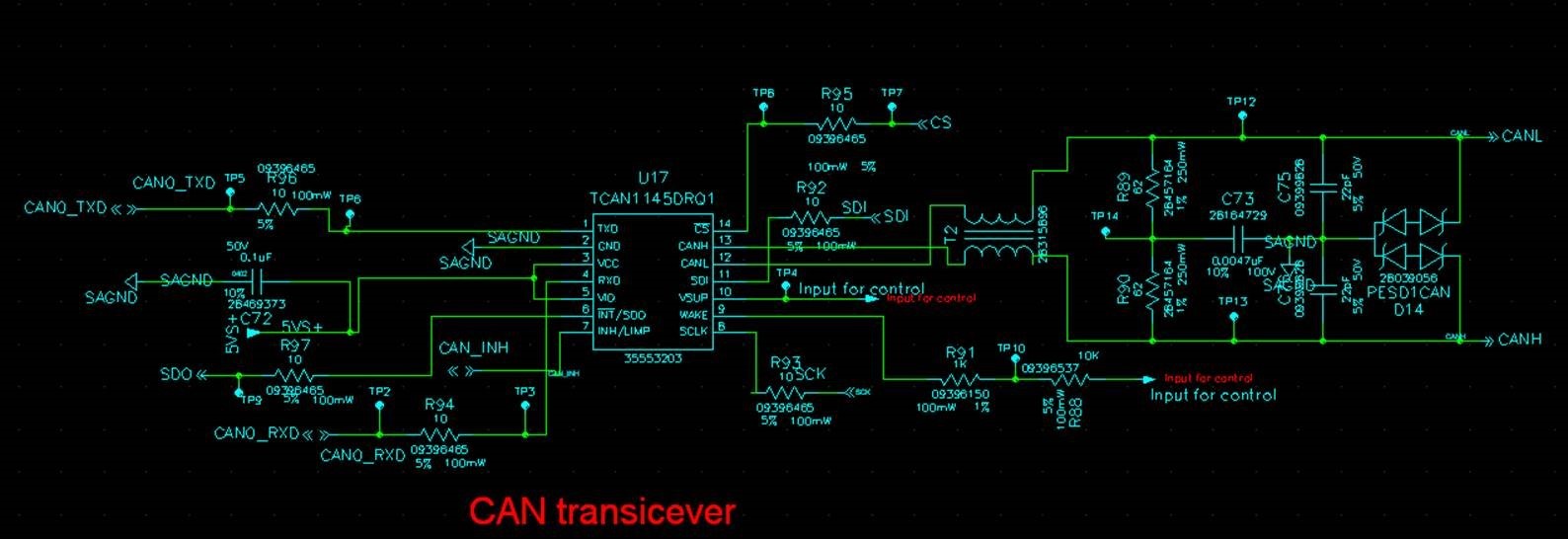
Could you please help review the schematic as below,

In addition, they don't use WAKE pin, so we should connect this pin to the GND directly, no need the pull down resistor, right?

Thanks & Best Regards,

Sherry

  • Hi Sherry,

    Pinout on schematic matches pinout on datasheet: Correct

    Resistors and Capacitors on Wake PIN and VSUP : If you intend not to use the WAKE pin you can just tie it to GND as you said. However you would still need a decoupling capacitor on VSUP. 

    Decoupling Capacitors Included and Valued Well: I do not see a decoupling capacitor on VSUP. The decoupling cap on VCC and VIO is valued well however we recommend having two decoupling caps one for VCC and one for VIO.

    VIO pin and VCC have power: Correct

    I would double check the wattages of all your 10 ohm resistors. I'm not sure what the VOH is for your input terminals but for the output terminals (RXD, SDO) on the TCAN1145 the min VOH is 0.8*VIO which in your case would be 4V. With 10 ohm resistors you are drawing 1.6 W.

    If these are just placeholders for you to solder on different resistors its fine.

    CAN Bus

    Split Capacitor, and Termination resistors included and valued well: Correct

    TVS diodes included: Correct, Make sure the placement is close and along the signal path.

    CMC included: Correct

    Best,

    Chris

  • Correction-

    I would double check the wattages of all your 10 ohm resistors. I'm not sure what the VOH is for your input terminals but for the output terminals (RXD, SDO) on the TCAN1145 the min VOH is 0.8*VIO which in your case would be 4V. With 10 ohm resistors you are drawing 1.6 W.

    If these are just placeholders for you to solder on different resistors its fine.

    These wattages for the series resistors are actually fine. Since each of the pins are driving a high impedance input the current is very small. A higher wattage rating would be needed for these resistors to survive a short on the input side of the resistor. However, this is uncommon and in most cases these resistors would just act as a fuse before anything gets damaged.