


Hi all,
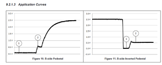
In the datasheet 9617A, the two figures shown below (figure 10 and 11) are the pedestal curves that occur at the B-side. Would someone explain, in which two situations these pedestals occur as they are not alike? Are they taken for different modes of I2C operations or they are the curves taken in the same operation mode but with different pull up resistors? In either case, the datasheet does not mention the setup environment. Please explain why are they different?
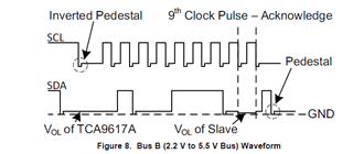
Another question, the pedestal and inverted pedestal in fig 8 are specifically shown with SDA and SCL lines, respectively. Is Pedestal associated to SDA and Inverted-Pedestal associated with SCL only?
Thanks for the help.
UF
