This thread has been locked.

If you have a related question, please click the "Ask a related question" button in the top right corner. The newly created question will be automatically linked to this question.

DP83822I: problems with Strap resample after PHYRCR[15] SW reset

Part Number: DP83822I

Hello, 

I'm working with a board in which your device is driven with a MAC whose GPIO are in weak PU after reset.

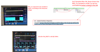
This causes a wrong sampling of RXD0-- RXD3 strap resistors. The device's reset is shared with the MCU, so my only option for a correct sampling of the strap resistors is to 

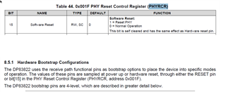
force SW reset by means of PHYCR[15] after having disabled the  PU resistors in the MAC's GPIO.

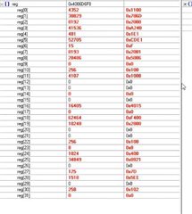
The configuration of Strap Latch-In Registers SOR1 and SOR2 after the physical reset is:

SOR1=0x5FD3;

SOR2=0x5

The PHYCR reset is launched waiting long enough (couple of seconds) after the GPIO configuration in order to let the nodes stabilize to the expected value.

what I see is that after reset is complete nothing changes in the values of SOR1 & SOR2.

Do you have any suggestions?

Another question: if I wanted to counter the weak PU with an additional PD, How far can I go with the value of the external PD in order to avoid stressing the phy's output buffer?

thanks so much for your support

Best Regards, 

G

  • Hi Giulio,

    By default, the RX_D3/GPIO_3 pin should have the default functionality of RX_D3, so bits[10:8] of register 0x0462 should be 000 and the pin should have a PD on power-up or reset.

    1. Can you check if the above is the case?
    2. Does this incorrect sampling of the strap resistors also happen during power-up?
    3. Is this an issue with just the RX_D0 to RX_D3 strap pins? Or are there other strap pins where this is the case as well?
    4. What are the SOR1 and SOR2 values before the reset? What values are you expecting? If they are the same, you can just post one set of values.

    Regards,

    Adrian Kam

  • Ciao Adrian, 

    Thanks for your fast reply, 

    My problem is that at power-up I cannot control the strap resistor because of the weak pullup of the MCU, and unfortunately there's no way in this board to separate the PHY reset MCU reset. The triggered values of SOR1 and SOR2 at powerup are coherent with what is expected due to the presence of PU.

    My idea is to disable the GPIO PU after poweron and then issue a SW reset via PHYCR[15] - This, according to what is written in the phy's DS, should trigger a new sampling with the correct configuration.

    The issue is with all the py strap with internal PD  (RX_D0... RXD3 & RX_DV) strap pins because the internal PD of the PHY is coutered by the presence of the MCU PU, so the sampled voltage is greater than the expected and they sample Mode2 instead of Mode1.

    So the sampling at poweron is correct, what that appear strange to me is that after the SW reset with MCU_PU deconfigured  I still see the strap configuration from the poweron.

    Thanks

  • Hi Guilio,

    One option I can suggest is to instead write to the registers after a reset to get the correct configurations. Since the issue seems to be reading mode2 instead of mode1 for the RX strap pins, the only things that change will be AN_1, EEE_EN, FLD_EN, AN_EN, XI_50. These are settings that can be changed through register writes.

    Regards,

    Adrian Kam

  • Ciao Adrian, 

    I will try that for sure, but why  doesn't the device  behave as  indicated in the datasheet  (see picture) ?

    If I wanted to compensate the weak PU at poweron with an external PD, how big can be the PHY GPIO's output current?

    This is important in order to assess the Pulldown resistor..

    thanks

    G

  • Is it possible that I am not writing the PYCR[15] correctly?

    How can i verify that the reset was actually performed?

  • Hi Giulio,

    If the strap settings in the register are different from what you intended, that usually means that the voltage on those strap pins at power up or restart is not the same as the voltage for the mode you want, as specified in section 8.5.1, table 10 of the datasheet. You are free to use an external pulldown to try and hit the target voltage when resetting, but since you stated that the settings are correct on power up, that may be changed with the addition of a pulldown.

    As for verifying reset, one way to check it is to look at RX_CLK. If the reset went through, then there would not be a proper clock on that pin during reset.

    Regards,

    Adrian Kam

  • Thank you, I will check RX_CLK and I'll let you know.

    Ciao

    G.

  • No problem. I am looking forward to the result.

    Regards,

    Adrian Kam

  • Hello Adrian, 

    As you can see from the pic,  the RX_CLK is stopping after the monitor GPIO_TRIGGER positive edge ( just before the SW_RST via PHYCR[15].

    Unfortunately, as you can see from the acquisition related to register SOR2, despite the fact that RXD_3 is @0V, nothing changes.

    This behavior is unexpected according to what is stated on the datasheet.

    What are we missing?

    Another question: we are thinking, in a future revision of the board, to separate the reset of th ePHY from the MCU one. The MCU might control the phy reset with a dedicated GPIO. Can you see any problems with that?

    Thanks

    G

  • Hi Giulio,

    I have a few questions:

    1. What does GPIO_TRIGGER do? Does it trigger the register write that resets the PHY?
    2. Would you be able to provide a schematic of your board? You can email it to me if it is something can cannot be shown on a public forum like E2E?

    As for your question, I do not see any problems with that. There are many cases where the RESET pin of the PHY is controlled by a GPIO on the MCU.

    Regards,

    Adrian Kam

  • Ciao Adrian, 

    The trigger is exploited to "trigger" the scope just before the reset is performed.

    As for the schematic, I should be able to send you privately the relevant part the relevant part, I just need to  know how:-) 

    The phy is connected without external straps, so it should be able to sample the correct configuration after the phy reset.

    Can you confirm that what is written in the datasheet is actually performed?

    In the next development we will perform, as you confirmed, a separate reset via GPIO, but now we need to fic this issue with a sw patch.

    Thanks for your valuable support

    G

  • Hi Giulio,

    You can send the schematic through the email shown when you click on my profile. Although, I mainly want to confirm that those RX strap pins are only connected to the MAC device and nothing else.

    Also, I can confirm that what is written in the datasheet is performed.

    Regards,

    Adrian Kam

  • Hi Guilio, 

    After looking at the schematic, I did not see anything wrong. Can you check and provide the voltage values of the strap pins on power up and on reset? It would be good to compare as well when the PU's are disabled and enabled to double check that the PU's are indeed disabled and to ensure there are no other voltages on the pins. 

    Regards,

    Adrian Kam

  • Ciao Adrian, 

    Upon reset (the physical one via reset pin) the value of the  strap is at about 0.5V (because of the presence of the  MCU's WPU). in this condition the phy samples RXD_0 to RXD_3  ( which are the phy's straps with internal PD ) in mode 2.

    When the MCU is operational I remap the relevant GPIO's in input mode without any PU and, as you can see from the  image above, RXD_3 ( but the same applies to the others RXD_x pins) is at about zero. this value is compatible with mode 1 and should be sampled accordingly.

    In the image you can see that the strap is sampled in mode 2 (either by the frequency of the clock and the value of sor2).

    regards, 

    G

  • Hi Giulio,

    After experimenting in the lab, it seems that the datasheet is incorrect, and that straps are not resampled using the reset by setting PHYCR[15]. However, resetting through the reset pin will resample the straps, but for your system that is probably not possible. As a result, the best option would be to configure the settings you want through register write after the software reset.

    Since you want RX_D0 to RX_D3 and RX_DV configured to mode 1, that would mean you want the following configurations:

    • Auto-negotiation enabled with all speeds and duplex modes advertised.
    • MII mode with 25 MHz reference clock
    • Fast link drop disabled
    • EEE disabled (on the sent schematic, it seems RX_D1 is strapped to mode 2, which would enable EEE. Let me know if this is a mistake)

    Let me know if I got something wrong. The PHY address does not seem to change between mode 1 and mode 2, so we do not have to worry about it.

    While I cannot provide a specific script since I am not familiar with the method you are using to write to registers, I can provide the steps/configurations needed.

    1. To enable auto-negotiation with all speeds and duplex modes advertised:
      1. Set bit[12] of register 0x0000 to 1 to enable auto-negotiation
      2. Set bit[8:5] of register 0x0004 to 1111 to advertise all speeds/modes
    2. To set MII mode with 25 MHz reference clock:
      1. Clear bit[9] of register 0x0017 to 0 to disable RGMII
      2. Clear bit[7] of register 0x0017 to 0 to configure for 25 MHz reference clock
      3. Clear bit[5] of register 0x0017 to 0 to enable MII
    3. To disable fast link drop:
      1. Clear bit[10] and bits[3:0] of register 0x000B to 0
    4. To disable EEE:
      1. Clear bit[0] of register 0x04D1 to 0

    Let me know if you need anything else, have anymore questions, or if I missed anything

    Regards,

    Adrian Kam

  • Thanks Adrian, 

    that was what I feared:-)

    The explaination is pretty accurate, I should be able to put in place what you are suggesting.

    I will try to implement the sw reconfiguration and I will give you the feedback as soon as possible.

    Another question: with a separate reset driven by the MCU,  do you have any suggestion on how to manage the reset pin at startup?

    I mean..  do you believe we should tie the reset pin via PU resistor/which value? 

    Best Regards, 

    G

  • Hi Giulio,

    In section 7.21 of the datasheet, figure 1 shows the power up timing and sequence that you should follow. As long as the reset pin goes high along with VDDIO during startup, it should be fine. Often times, a 2.2k resistor is used as a pull up on the line. When you want a reset to occur, the MCU will pull the line low, which triggers a reset on the PHY. I have also seen implementation without a pull up where the MCU constantly provides a high signal to the reset pin, until a reset is triggered and the signal goes low.

    Regards,

    Adrian Kam

  • Thank you  Adrian for your valuable and swift support!!!

    Have a nice weekend :)

  • Hi Giulio,

    No problem. Let me know if your issue gets resolved, or if you have more.

    Regards,

    Adrian Kam

  • Ciao Adrian, 

    I wrote the patch but It seems that after this piece of code is executed the phy is no longer responding.

    After writing regulars and extended registers I read them back in order to verify that the value is correctly written.

    I'm doubleckecking the code, meanwhile do you have any idea?

    thanks

    G.

  • Hi Giulio,

    Can you go into more detail about what part of the PHY is no longer responding? Are you no longer getting link? Can you read the registers? Are you not able to send packets?

    1. Is the PHY stuck in reset mode?
    2. Can you try only writing for the auto-negotiation and MII registers (ignore fast link drop and EEE)?
    3. Can you provide the table of expected strap configurations vs what you are seeing? I want to double check to make sure I did not make a mistake in my assessment of what configurations you need?

    Regards,

    Adrian Kam

  • After the patch the link does not come up any longer.

    I can read back the registers and their value is as expected. 

  • Hi Giulio,

    Another thing you can try is that after performing all the register configurations, perform a digital restart by setting bit[14] of register 0x001F. This will restart the internal state circuitry, but not the registers.

    Regards,

    Adrian Kam

  • Hello Adrian, 

    Half good news, 

    After the digital restart the phy seems correctly configured to 100MHz Full duplex. Find Below the full set of registers

    We still got some stability problems though and I suspect that the prototype I'm working with (at home) , not in a good shape, cannot go past 10Mb/s.

    Tomorrow I'll verify  the patch with a better hardware and I'll let you know.

    regards, 

    G

  • Hi Giulio,

    Looking forward to seeing how things go.

    Regards,

    Adrian Kam

  • Ciao Adrian, 

    I can confirm that the phy can now negotiate 100Mbit Full duplex!!!

    Thank you for your valuable support.

    Best Regards, 

    G