This thread has been locked.

If you have a related question, please click the "Ask a related question" button in the top right corner. The newly created question will be automatically linked to this question.

TS3DV642: TMDS Signals lines trace Impedence

Part Number: TS3DV642

HI ,

this is a follow up question to my previous forum post   

https://e2e.ti.com/support/interface/f/interface-forum/976585/ts3dv642-3-1-mux-solution/3610027?tisearch=e2e-sitesearch&keymatch=%20user%3A476769#3610027

We have sucessfully finished the schematic design as per solution 2 mentioned in the post

For setting the layout constrains i have few doubts.

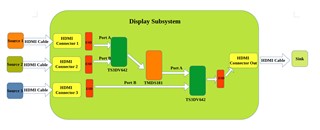
– R ON mintioned in datasheet for TSDV642 is as follows
– Port A: 6.5 Ω
– Port B: 8.2 Ω

and the HDMI 2.0 Impedences for differential pair are as follows

  1. Each TMDS signal shall have single ended impedance of 50 Ω ± 10%.
  2. Each TMDS pair shall have differential impedance of 100 Ω ± 5%.

So My question is should i reduce the R ON resistance from specified impedences on coresponding ports (A and B) ??

If so, what would be the coresponding single ended and differential impedences??

Regards

Sreekanth MK

  • Sreekanth MK

    The TS3DV642 Ron will add to the board trace impedance. So one side of the TS3DV642 will have the board trace impedance, and the other side of the TS3DV642 will have board trace impedance + Port A or B Ron. 

    Where did you get the spec of differential impedance of 100 +/-5%? The HDMI spec actually defines the differential impedance to be 100 +/-15%. If you try to have differential impedance of 100 +/- 5%, then the TS3DV642 Ron spec is outside the limit. But if the differential impedance is 100 +/- 15%, then the TS3DV642 Ron can meet this requirement.

    Thanks

    David