Because of the holidays, TI E2E™ design support forum responses will be delayed from Dec. 25 through Jan. 2. Thank you for your patience.

This thread has been locked.

If you have a related question, please click the "Ask a related question" button in the top right corner. The newly created question will be automatically linked to this question.

TCAN1051V-Q1: TCAN151V CAN bus communication issue

Part Number: TCAN1051V-Q1
Other Parts Discussed in Thread: TCAN1051, SN65HVD230

hi,

I encountered an issue where the TI TCAN 1051 is interfering with the CAN bus. Below is the test setup:

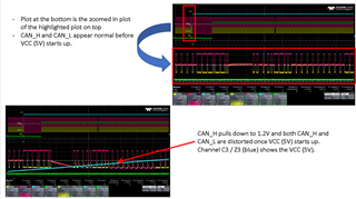
This was simulated by connecting an unpowered DUT where the TCAN1051 transceiver is used to a powered CAN simulator.  In this scenario, the CANH and CANL signals are within the specifications. 

The DUT was then powered where the 5V is powered first before the 3.3V and the CANH and CANL are pulled low which will affect the messages that the other devices connected on the CAN bus will read.


The CAN transceiver, TCAN1051 should not be pulling the bus below its specification.
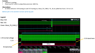
Please advice what is the reason the CAN BUS behave this way? (e.g pulled low from 2.5V to 1.2V???)

Best regards,

Felix

  • Felix,

    Thanks for bringing this to E2E. Supply the VCC but not the VIO will put the device in a protected mode where the bus impedance shifts, but it should not be pulling the bus to 1.2V. ,

    I've notified an expert on this device of this thread, and they will respond accordingly.

    Regards,

    Eric Hackett 

  • Hi Felix,

    As Eric stated, this supply configuration will put TCAN1051 into a protected mode, leaving the bus pins in a high impedance state. In this state, this transceiver will not actively bias the bus to 2.5V and will instead only present a high impedance leakage path to ground. The leakage path in this protected mode is more significant than an entirely unpowered state. However, it should not be significant enough to disallow communications in most systems. 

    Other active transceivers on the bus may continue biasing the bus to a recessive voltage (~2.5V). However, these biases are intentionally weak so they do not contest any transceiver attempting to drive a dominant state to the bus. Because of this weak bias, small leakage paths on the bus can have significant impacts on recessive voltage. What we're likely seeing in your system is the one active transceiver on the bus is unable to bias the recessive level to 2.5V because of the increased leakage of TCAN1051 in protected mode. Before 5V is supplied, the device is powered off with an even smaller leakage path, so the simulator transceiver has no problem biasing the recessive level. When both supplies are active, the simulator and TCAN1051 work together to bias the bus to 2.5V and no significant leakage path is present. If more transceivers were active on the bus while TCAN1051 was in its protected mode, each active transceiver would contribute to the bias and a recessive level closer to 2.5V could be achieved. 

    Lastly, I want to state that a decreased recessive level from 2.5V will not impact signal integrity in most systems. Because the protocol works off the differential of the two CAN lines, as long as CANH and CANL recess to the same level the integrity of the signal is retained. A non-symmetrical transition in these signals due to a lower recessive level may impact systems that operate at very high data rates, have complex network topologies, or are particularly concerned with emissions. 

    Let me know if this is clear and if you have any concerns about how this may impact your design. 

    Regards,
    Eric Schott

  • hi Eric,

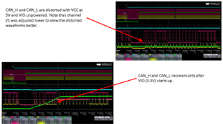
    Our setup is actually just the EUT with the TCAN1051 transceiver connected directly to the CAN simulator.  There are no CAN devices connected to the CAN bus which means that it’s only the TCAN1051 that is pulling the bus low.  Please refer to 2 waveform captured below.  CAN_H and CAN_L are distorted once the VCC (5V) powers up and will only recover after VIO (3.3V) starts up.  The distortion of the CAN waveforms is not acceptable as other devices connected to the CAN bus may miss critical data.  This is not acceptable.

    Best Regards,
    Felix

  • Hi Felix,

    I understand that these waveforms are not indicative of a healthy CAN network. This is due to the fact that half of the network is in a protected mode. Once this device is placed on a bus with other active nodes, the other biasing transceivers will be able to accommodate for the leakage of the underpowered TCAN1051. This will result in a network that is proportionally more active (2 powered nodes, 1 protected node) and the distortion will be significantly decreased. 

    In this system, is it intended that communication will be taking place during this protected state? In most CAN systems that don't implement partial networking, all connected CAN nodes will become active once bus communication is detected. Is it planned to have a TCAN1051 node to power-on with this ramp while there is other traffic on the CAN bus? If so, how many nodes are expected to be active during this state?

    Regards,
    Eric Schott

  • hi Eric,

    The device can be considered as an aftermarket product where it can be installed on a system with different CAN devices.  We have encountered a similar issue before where the CAN bus was affected and distorted by the CAN transceiver start up and this caused major issues as critical information was missed.  Therefore, the best is to avoid the CAN from being distorted and disrupted.

     The device where the TCAN1051 is mounted can be powered up / down separately from the rest of the system so the concern is that the device will affect the CAN bus in this configuration.  The devices connected to the CAN bus can be powered independently from each other so it’s imperative that our device with the TCAN1051 doesn’t affect the CAN bus at all. 

     To answer the questions, communication should go on when the TCAN1051 powers up / is in the protected state.  Traffic on the CAN bus should continue and the TCAN1051 should not affect the CAN bus.  The device will be mounted on different systems that may have different number of nodes connected.

    In this case, do you suggest us to use alternative CAN bus IC for this case? I saw at forum (+) TCAN1051V-Q1: STM32f091 interface not working - Interface forum - Interface - TI E2E support forums got mentioned another CAN bus sn65hvd230 don't have such issue. 

    As I mentioned this is after market product, we really dont know how many CAN nodes will be there t= in the final network.

    No sure will this help?

    Best regards,

    Felix

  • Hi Felix,

    Thank you for describing the issue this will cause in your end equipment. 

    I believe switching to a 3.3V transceiver may be a valid solution as this would eliminate any scenario where the device is partially powered (only one Vcc source for 3.3V transceivers. However, if the goal is to have minimal impact on the bus, a 3.3V transceiver may also not be the best solution as these devices will not be able to contribute the same CANH dominant voltage as 5V transceivers. This, like the leakage from the protected TCAN1051, would have only a small impact on the bus, but it sounds like this is a great concern for this implementation. 

    For ideal passive behavior from a 5V CAN transceiver, I could recommend using a non-V variant of TCAN1051 (pin 5 is NC) so that no protected mode would be entered during powerup. If 3.3V logic in needed, an external voltage translator would need to be included on the RXD line to the controller (could be a simple FET will pull-up to Vio). The TXD input is compatible with 3.3V input logic with a Vih threshold of 2V. Does this solution sound possible for this design?

    Regards,
    Eric Schott