Other Parts Discussed in Thread: TCAN4550
Hi team,
Could you give me your advice about the waveform disturbance due to the Common Mode Choke Coil(CMCC)?
*The waveform becomes clear when the CMCC is removed.
My customer use ''DLW32SH510XK2''.(https://www.murata.com/en-us/products/productdetail.aspx?partno=DLW32SH510XK2%23)
*Schematic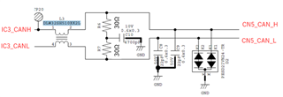
*Waveform
[1]
IC3_CANH/L : Input
CN5_CANH/L : Output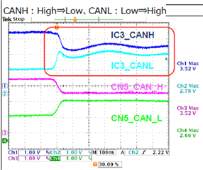
[2]
IC3_CANH/L : Output
CN5_CANH/L : Input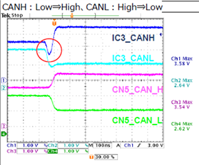
I think this phenomenon is causing the CMCC.
What kind of SPEC do you think is influential?
If you have recommended coil, please let me know.
And then, about waveform No2, I think the undershoot is large at rises up.
Why does it happen?
Sincerely.
Kengo.