This thread has been locked.

If you have a related question, please click the "Ask a related question" button in the top right corner. The newly created question will be automatically linked to this question.

THVD1550: terminal resistor selection

Part Number: THVD1550
Other Parts Discussed in Thread: THVD1500, THVD1510

Hi team,

I have a question about terminal resistor selection of THVD1550.

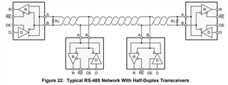
does the terminal resistor is must? how to select the Rt value?. I ask this is becasue in the datasheet, Figure 22, not all THVD1550 add terminal resistor. could you help comment what condition need terminal resistor?

in additional, if customer use difference vendor RS485 IC, the one side doesn't add terminal resistor, and THVD1500 side add Rt, is it ok ? any problems?

thank you

  • Hi Betty,

    These are all good questions. There's a lot to understand about termination networks in RS-485 systems and how to best implement them to receive the most benefit. John Griffith has a nice blog post outlining a lot of this information with some nice graphics too. I'll summarize some of the answers to your questions for quick reference below. 

    does the terminal resistor is must? how to select the Rt value?

    Termination resistors in RS-485 systems are most often needed to dampen signal reflections by matching the impedance of the cable being used. Typical cable used in RS-485 networks has an impedance of 120-ohms, thus most RS-485 transceivers are characterized with 120-ohm termination resistors (loads of 60-ohms representing two resistors in parallel or 54-ohms to represent additional load from other transceivers are also commonly seen). The majority of RS-485 systems should implement termination resistors at the two end-points of a system with a resistor value matching the characteristic impedance of the cable. 

    in additional, if customer use difference vendor RS485 IC, the one side doesn't add terminal resistor, and THVD1500 side add Rt, is it ok ? any problems?

    Because the termination resistor is valued based off of the characteristics of the cable, switching transceivers will most likely not warrant a change in termination. Where this may become significant is when A) the drive strengths of the transceiver vary and one is unable to drive the load of the bus, or B) when one transceiver causes more reflections or noise in the system requiring a more ideal termination method.

    A) To address the first case, the system designer must ensure that the bus is not overloaded to the point that a transceiver may struggle to drive a valid differential. This is why only two termination resistors (when using ~120-ohm values) should be used on the bus to present an equivalent load of 60-ohms. If this load increases past a transceiver's driving capability, the bus will no longer be able to carry valid data. 

    B) The second case is more often a problem when the network is already experiencing reflections from sub-optimal layout or termination. Regardless of the transceiver used, the best practices for these system characteristics should be followed to reduce the influence this has on the signal - simple bus topologies should be used with short stub lengths and termination matching the impedance of the cable should be placed at the two furthest nodes in the system. When optimal conditions are not possible due to other system constraints, different transceivers may offer a solution that performs better than other devices. An example of this would be if a THVD1510 with a slow data rate is used in place of a THVD1550 with a much higher one. Doing this decreases the amount of high-frequency energies introduced to the bus which are more likely to be reflected and cause ringing. The tradeoff is that the data rate of the system will be limited by the slew rate of the slower transceiver. 

    Let me know if this is clear or if there's anything else your curious about. I'm happy to answer any questions you have about John's blog post as well. 

    Regards,
    Eric Schott

  • Many thanks Eric.

    I still have a few question about 2. as you mentioned, it still suggest to add 120ohm on both RX and TX, right?

    their application is one to one, no other nodes.

    since the other side is designed by another account and use different IC vendor. my customer have concern that if they add a 120ohm terminal resistor, and the other side doesn't add, will have problem. 

    thank you

  • Hi Betty,

    Termination should be placed on the RS-485 bus (A and B lines) at the two nodes that are furthest from each other. This is simple in a point-to-point system, but is also the best practice for larger ones. An example of this can be seen in THVD1550's datasheet:

    The termination value is based off of the cable impedance and two 120-ohm termination resistors will be fine for any RS-485 transceiver that supports the electrical standard. You should make sure that the bus is not already fully terminated (has equivalent load of ~60-ohms) before adding another termination resistor. Doing so may overload the bus and make it impossible for any transceiver to drive a valid differential signal. Do you know what the termination scheme is for the rest of the system? If the system is already well established, chances are it is already properly terminated and any additional middle nodes will not need to add termination resistors.

    Regards,
    Eric Schott