


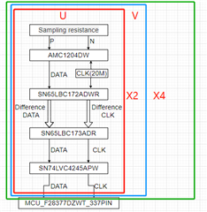
Error code of current sampling in current loop of servo motor,The project uses DSP (28377) to control 4 motors,Each motor samples the U-V two-phase current, and the sampling diagram is shown in the following figure:

I have a problem. When only one or two axes are sampled for current sampling, there will be no bit error. When three or more axes are used for current sampling, there will be bit error in current sampling, and a large current peak will appear after analysis.
When we remove the level conversion chip (sn74lvc4245apw) and change the power supply of differential to single ended chip (sn65lbc173adr) from 5V to 3.3V, this problem is solved. We have ruled out the possibility that 5V and 3.3v power supply is insufficient. I still have doubts about the emergence of this problem and why this operation can solve this problem. Hope to get the answer here.
Remove the level conversion chip, modify the chip power supply voltage, as shown in the figure below

If you need more data, please let me know,To solve this problem together.
485 chip (sn65lbc173adr) power supply is shown in the figure below:

The typical power supply value of this chip (sn65lbc173adr) is 5V, and the minimum value is 4.75V. However, when I use 3.3V power supply, the system still works normally. I want to know what unstable factors and problems may be caused when I change 5V power supply to 3.3V power supply.
