This thread has been locked.

If you have a related question, please click the "Ask a related question" button in the top right corner. The newly created question will be automatically linked to this question.

THVD1429: The THVD1429 failed at 2k surge test

Part Number: THVD1429

Hi Team,

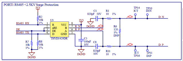
Our customer used THVD1429 on their board but during certification tests, the chip failed at 2kV surge test. The failure mode is short circuit of data+ data- to VCC and GND. I understand that the device can withstand up to 2.5kV surge voltage. 

Here are additional information from the customer.

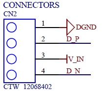
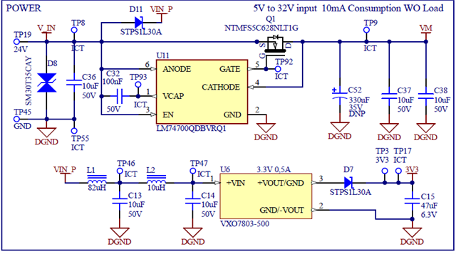
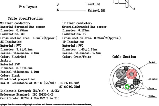
  1. The PCB is tested through a cable connected to CN2 (4meters). This cable routes VIN (5-32V, 24V nominal), DGND, Data+, Data -.
  2. The Surges tests at 1kV into VIN and DGND signals  is OK.
  3. The Surges tests at 2kV into VIN and DGND signals  is not OK as the THVD1429 chip is short-circuited internally through Data+ & Data- & 3V3 & DGND. (the rest of the PCB electronics are alive).

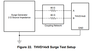
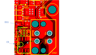
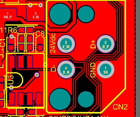
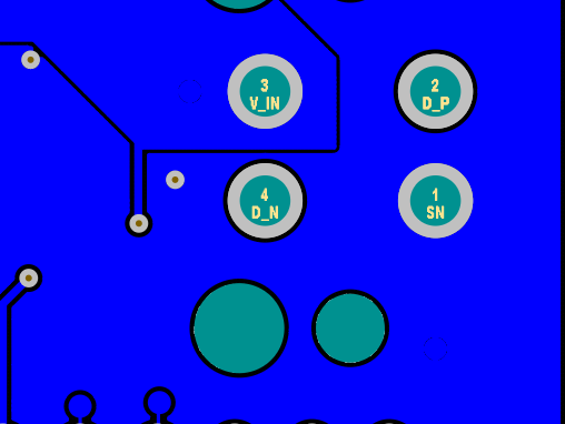
Here are the schematic diagram, PCB layout and some information about the surge test.


Top Layer

Bottom Layer

Can you please help us solve this issue?

Thank you for your support!

Regards,

Danilo

  • Danilo,

    Can you elaborate the detail of surge test? THVD1429 passes the 1.2/50us surge test with 40Ohm (2 parallel 80Ohm) series resistance.

    In term of peak current, the peak is about 62.5A. Also the DUT is unpowered per IEC 61000-4-4 standard.

  • Hi, according to the certification center, the test is being perfomed as dc power lines definition, and the suggested coupling network applies for I/O signals test. The fail has occurred during a 2kV surge in VIN vs DGND not during 2kV surge in Data+ vs Data-.    

  • Different tests have different coupling network. This app note has good information.

    Demystifying surge protection

    For communication lines, the strikes are with respect to ground.

  • Hi Hao L, Thanks for your reply. Yes, we know. I was just adding that the THVD1429 chip died during DC power testing lines not during Signal testing. I don't know if during the testing the surge was able to coupled along the outer cable causing the THVD1429 to fail (without 40ohms coupling network during this dc power surge test). Would it be possible? Could this kind of surge shortcircuit VCC, GND, D+ and D- at the THVD1429? 

  • Jorge,

    I see. I'm sorry it took me a while to understand your question. I'm not an expert in the power design. However I think the possible explanation is that the energy is diverted (coupled) to unexpected places. Can you confirm both A and B got damaged? Can you tell each one is short to Vcc or ground? I don't see D8 in the layout. Is it close to the connector? How about C36? I'm not sure if D_P routing is too close to V_IN. If it's the case, increasing C1 and C5 may help. Another point is to make the bypass capacitor C5 close to the IC and choose 1uF.

  • Hi Hao, thanks for your suggestions. I attach a new picture of top layer, to clarify the location of components. The idea of increasing the C1, C5 and C8 value is interesting, as the problem may be caused due to problem related to differential mode or common mode absolute max (15V I think). 


    The IC THVD1429 that died has VCC to GND to D+ to D- shortcircuited (all pins together), Another point that the certification center added to me is that the chip died after several surges (as you know the IEC61000 describes that the test are several surges pulses) so the problem didn't started after the first pulse.

    Thank you for your help

    Regards

  • Jorge,

    I think the component locations are good. Since U11 and U6 are OK, I guess the path might somehow bypass this part of circuit. If the chip was not damaged immediately, the current/voltage leaked to THVD1429 might just barely above the abs max. I'm not sure if you have any software to do some analysis. Another thought is that you could add TVS at different locations (Vcc to GND, D+ to GND, D- to GND, D+ to D-) one at a time to see which case helps. You might get the clue backwards. 

  • Thanks for your reply. Adding componentes (like TVS) is not easy  as we haven't got extra footprint for them, but we are going to test with serial ptc at D+ D- (R1, R11). Regards