This thread has been locked.

If you have a related question, please click the "Ask a related question" button in the top right corner. The newly created question will be automatically linked to this question.

LAUNCHCC3235MOD: J14 connector reference

Part Number: LAUNCHCC3235MOD
Other Parts Discussed in Thread: UNIFLASH, CC3235MODSF, TMDSEMU110-U

Hi TI,

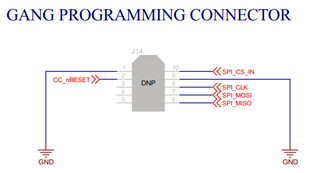
Could you please tell me the reference of the J14 connector on LAUNCHCC3235MOD? I could not find it in the BOM.

BR,

Brahim

  • Brahim,

    J14 is not a component. It is a footprint for Tag Connectors.

    BR,

    Seong

  • Hi Seong,

    Where I can find this footprint ? what component to use for the layout (schematic and footprint)?

    BR,

    Brahim

  • Brahim,

    I am unable to share the symbol and footprint from our database, but I did a quick google search and was able to find this: https://www.snapeda.com/parts/TC2050-IDC/Tag-Connect%20LLC/view-part/

    See if this will work for you.

    BR,

    Seong

  • Hi Seong,

    Will this connector of 10 pins work with XDS110 debug probe that has a port of 14 pins?

    BR,

    Brahim

  • Brahim,

    What is your goal? Based on this thread and your other one here, it seems like you have a XDS110 debug probe and a tag connector. And you want to directly program the SPI serial flash that is internal to the module.

    From the image Figure 3 that you share in your previous post, there are only JTAG and UART signals, so you will not be able to program the SPI serial flash with this. Instead, you will need to use a SPI programmer.

    With the equipment that you have, I recommend you use UART to program your module using UniFlash. This means you'll need to connect to the module pins 46 and 47. Ensure there are 100k pull up resistors tied to these pins.

    BR,

    Seong

  • Hi Seong,

    What you said is exactly my goal.

    I am using CC3235MODSF launchpad, why do I need to connect the pins 46 and 47 with 100k? I cannot just use the JTAG connector (J2)? if yes, could you please provide me with a cable referrnce compatible with the JTAG connector to connect it to the PC and flash the memory with Uniflash?

    Thank you !

    BR,

    Brahim

  • Brahim,

    Please see the CC3x3x Uniflash User's Guide here and the CC3235MOD Production Line Guide here.

    If you are using Uniflash to program the serial flash through the CC3235, you must use UART. To use this option, you must connect to the device's UART pins, pin 46 and 47, which require 100k pull ups.

    Another option is for you to generate your programming image using Uniflash, and using an external off-the-shelf tool to directly program the the image to the SPI serial flash via SPI. If this is what you want to do, you must remove the external serial flash you have on the board because there is already an external serial flash internal to the module. Then you must use an off-the-shelf tool SPI programmer. You cannot use the XDS110 as it only has UART and JTAG.

    JTAG cannot be used to program the device. JTAG is only used to debug. Please see the CC3235 Technical Reference Manual on the JTAG debug interface.

    BR,

    Seong

  • Seong,

    I am using CC3235MOD launchpad board. Why do I need to add an additionnal connection to pins 46, 47 ? they are already connected to USB connector (J1) right ? 

    I want to flash the code in the external flash (32Mbit integrated in the module) using UART though USB connector (J1) which is connected to onboard xds110.

    BR,

    Brahim

  • Brahim,

    I thought you were referring to the TMDSEMU110-U debug probe as I got confused from your other thread which also mentions your custom PCB. The J2 connector is used with the TMDSEMU110-U and the ARM Cortex 10-pin converter adapter that comes with it.

    So now we're talking about just the LAUNCHCC3235MOD LaunchPad and you want to program the onboard CC3235MOD using UART by using the onboard XDS110. If you want to do this, you do not require any other hardware.

    Please see the LAUNCHCC3235MOD schematic that is included with the design files.

    So when connecting the Launchpad to the PC via J1 and using Uniflash, note that the signals from J1 go to U1, the MSP432E4 emulation MCU. Communication is then established via UART from the XDS_UART_RX and XDS_UART_TX signals which go to the voltage translators. Then finally to the module's UART pins, 46 and 47 and ultimately the UART pins of the CC3235 IC inside the module. The CC3235 IC then programs the serial flash via SPI. This is one way to program the serial flash. 

    The other way is to directly program the serial flash using the module pins 13, 14, 15, and 17 with an external SPI programmer.

    Hope this helps,

    Seong