Because of the Thanksgiving holiday in the U.S., TI E2E™ design support forum responses may be delayed from November 25 through December 2. Thank you for your patience.

This thread has been locked.

If you have a related question, please click the "Ask a related question" button in the top right corner. The newly created question will be automatically linked to this question.

DP83822IF: DP83822 Communication issue with fiber port

Part Number: DP83822IF
Other Parts Discussed in Thread: TLK105L

Hi team,

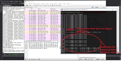
My customer is using DP83822 in their project with fiber port. However they met abnormal communication issue: After power up, communication is ok, if they plug out the fiber port and plug in again, then sometimes the communication will fail and the fail picture as showed in below picture:

Below are the registers value when normal communication and abnormal communication:

Normal situation registers:

MII PHY #1 transceiver registers(from 1st register to 32 register):

   2100 784d 2000 a240 01e1 0000 0004 2001

   0000 0000 4100 1000 0000 0000 0000 0000

   0005 0108 e000 0000 0000 0000 0100 00e5

   0400 8001 0000 007d 05ee 0000 0002 0000.

Basic mode control register 0x2100: Auto-negotiation disabled!

Speed fixed at 100 mbps, full-duplex.

Basic mode status register 0x784d ... 784d.

Link status: established.

Capable of 100baseTx-FD 100baseTx 10baseT-FD 10baseT.

Able to perform Auto-negotiation, negotiation not complete.

Vendor ID is 08:00:28:--:--:--, model 36 rev. 0.

No specific information is known about this transceiver type.

I'm advertising 01e1: 100baseTx-FD 100baseTx 10baseT-FD 10baseT

Advertising no additional info pages.

IEEE 802.3 CSMA/CD protocol.

Link partner capability is 0000:.

Negotiation did not complete.

#


For abnormal situation:

MII PHY #1 transceiver registers(from 1st register to 32 register)::

   2100 784d 2000 a240 01e1 0000 0004 2001

   0000 0000 4100 1000 0000 0000 0000 0000

   2a05 0108 8300 0000 00ff ffff 0100 00e5

   0400 8001 0000 007d 05ee 0000 0002 0000.

Basic mode control register 0x2100: Auto-negotiation disabled!

Speed fixed at 100 mbps, full-duplex.

Basic mode status register 0x784d ... 784d.

Link status: established.

Capable of 100baseTx-FD 100baseTx 10baseT-FD 10baseT.

Able to perform Auto-negotiation, negotiation not complete.

Vendor ID is 08:00:28:--:--:--, model 36 rev. 0.

No specific information is known about this transceiver type.

I'm advertising 01e1: 100baseTx-FD 100baseTx 10baseT-FD 10baseT

Advertising no additional info pages.

IEEE 802.3 CSMA/CD protocol.

Link partner capability is 0000:.

Negotiation did not complete.:

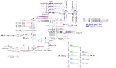
 Below are the schematic that customer used:


Pls note that(Customer use our TLK105L before, so here they use same symbol of TLK105L for DP83822, so some pin name is a little bit confused). We also tried to remove the R1014 and R1015 away, the issue still the same.

As customer may go to MP stage, can you help look into this issue, thanks a lot for your great support on this issue!


Best regards,

Sulyn

  • Hi,

    I believe you have Signal Detect of Optical Transceiver connected to DP83822 ( LED_1). What is the Optical Transreciever signal detect Polarity ?

    can you confirm the strap configuration on RX_ER ? We need it to be Mode 3( if RGMII disabled) or 4 ( if RGMII is enabled)

    Regards,

    Geet

  • Hi Geet,

    Thanks for the support! In fact, customer didn't use the Signal detection(As you can see they pull LED1 pin to high forever). They don't detect the signal from optical module.

    For the RX_ER, when we do the test, we let this pin open, that should be Mode 4 based on our datasheet.

    Thanks a lot for your support!

    Best regards

    Sulyn 

  • Hi Sulyn,


    We need to do both :
    - Connect signal detect from Optical Transreciever to LED_1. Check the polarity is aligned with default polarity of signal detect on DP83822.
    - Configure the RX_ER strap to mode 4.

    Regards,
    Geet
  • Hi Geet,

    The truth in customer side is they can't use the LED_1 to detect the signal from SFP, they don't want to check the status but make it always "signal detected" by pulling it high forever. This is customer's requirement.

    As for the RX_ER mode,we left this pin float which is Mode 4 yet.

    Based on customer's requirement, is these some software solution to avoid(Don't consider Rest solution)? Thanks.

    Best regards,

    Sulyn

  • Hi Geet,

    Can you help give feedback for the question, as it's in the MP stage, so it's important to support on this, thanks! If not, they will switch back to BCM5421 solution quickly.

    Best regards,

    Sulyn

  • We recomend to enable signal detect. Else, on fiber removal/connection, phy needs to be soft reset.

    Regards,
    Geet
  • Hi Geet,

    Thanks for the support! So If we recommend customer to do soft reset, how can customer know when to do the soft reset? Which registers should they monitor to determine when to do the soft reset after plug out the cable?

    Best regards,

    Sulyn

  • Hi Geet,
    Another question that I want to double check with you if customer don't use the LED1 pin as signal detection and they also set the SD_DIS(RX_ER set to Mode 3), what will be the problem during communication, based on customer's feedback, the communication is not stable, sometimes it's ping successfully but sometimes not, can you also help give some suggestion for this? Thanks.

    Best regards,
    Sulyn
  • To answer first question : Phy does not have any indication to indicate need for soft reset. Since cable plugging/unplugging is a manual event, it shall be handled at System level.

    Setting RX_ER to Mode 3 shall enable the Signal Detection. If LED1 pin ( Pull High/Low) will get reflected on the link status. With no cable unplugging, this communication shall remain stable.

    Regards,
    Geet
  • Hi Geet,

    So for the first question, do you mean these is no way that PHY can know that the cable was plugged out and plugged in, so customer can do the soft reset when get this trigger. Can you help think of some available solution for customer to go ahead? Thanks.

    For the second question, as showed in datasheet, when RX_ER set to Mode 3, the SD_DIS =1, which should mean that Signal detection was disabled if my understanding is correct, but you say it shall enable the Signal detection, can you help double confirm this? Because customer set it to Mode 3

    Best regards,

    Sulyn

  • Hi Sulyn,

    Yes, soft reset is needed to re-sync the phy.

    SD_DIS=1 : It's an error in datasheet. We are working on update of this field. You can read this field as SD_EN field.

    Regards,
    Geet
  • Hi Geet,

    Thanks for the information, we are now planning to use bit 9 of 0x0012 register to judge and do the soft reset to re-sync the phy, detailes as below:

    Monitor 0x0012 register, when the bit 9 of 0x0012 was detected as 1, then will do soft reset to re-sync the communication. This works well after several times test to avoid the unstable communication issue after plug out&in, but I need your help to check if this solution ok to use and any other potential problem that may have?

                phy_data = phy_read(phydev,  0x0012);

                   if( phy_data & 0x0200 )

                   {

                                  printk("phy reset\n");

                                  phydev->link = 0;

                                  phydev->speed = SPEED_10;

                                  phydev->duplex = DUPLEX_HALF;


                                  phy_write(phydev, 0, 0x8000);

                                  udelay(100);

                                  dp83822_config_init(phydev);

                                  phy_write(phydev, 0, 0x2100);

                   }


    Another import question that need to make clear that during the test, the register 0x0001 seems always showed 0x784D even when the fiber cable was moved(bit 2 is 1), which should no link, but it still showed link is good?Why it is like this? Is this because of the SD_DIS was EN_DIS like you mentioned?


    Best regards,

    Sulyn


  • Hi Sulyn,

    Yes, Usage of Signal Detect signal from Optical Transceiver helps fix the wrong Link-Up status in Register 0x0001. DP83822 usage the signal to reset the Link-up state machine on the signal. 

    On usage of bit 9 : why you choose this interrupt bit ? Are you observing this interrupt bit as n when the cable is removed and re-inserted ?

    Regards,
    Geet

  • Hi Geet,
    Thanks for the support! For bit 9 of register 0x0012 is because we found when cable was plugged out, the bit will be set to 1 every time, even when the cable was plugged in again before do the soft reset, that's why we use it and it works well after test. So not sure if this is a good way to solve this issue?
    Is these any potential risk and we have other solution to solve this issue by software?

    Best regards,
    Sulyn
  • Hi Sulyn,

    As discussed in email, please use the register 0x12 as an indication to initiate Reset on the PHY.

    -Regards,
    Aniruddha