This thread has been locked.

If you have a related question, please click the "Ask a related question" button in the top right corner. The newly created question will be automatically linked to this question.

tps65986: Debugging: Can't get DP working with TPS65986 + HD3SS460 mux

Part Number: tps65986

I have my own TPS65986 + HD3SS460 mux DFP implementation that I am trying to get working. I am trying to get a 4 lane DisplayPort + USB2 link working. I am using a TPS65986EVM module with sync board as the UFP and this is connected to a monitor over a DisplayPort cable. So far I cannot get video working. I am able to use a TPS65986EVM module with a source board to connect to the TPS65986EVM+sync board and that seems to work just time.

On my implementation, from what I am able to scope, the mux's Enable pin goes high when the UFP is connected. The AMSEL pin also goes high and the POL pin changes based on the polarity of the USB C cable plugged in. I can scope DP Aux data entering the TPS65986 and leaving on the SBU1/SBU2 pins. However I don't scope any data on the main displayport lanes. The chipset is correctly supplying power to the UFP when it is plugged in.

I am building my application on top of the TPS65986_HD3SS460_DFP_Advanced_v3_10.tpl project. When I apply this same firmware to the TPS65986EVM +source board instead of my implementation, the system works.

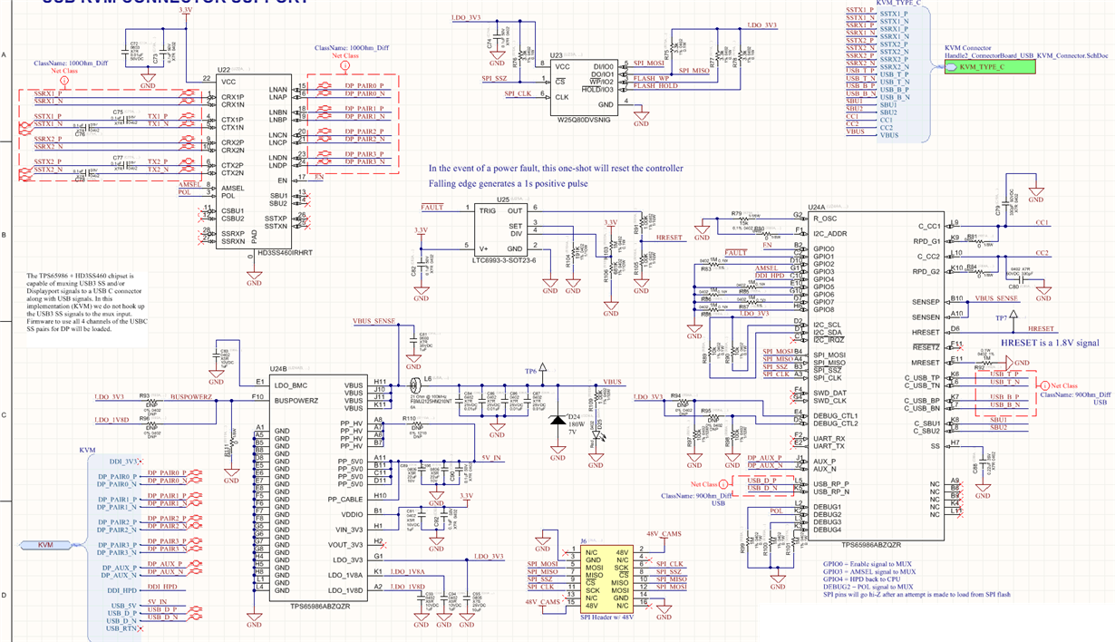
I'm pasting my schematic here to have a look at. I drew it based off of the schematic in the EVM user guide and the mux source/sync EVM user guide: http://www.ti.com/lit/pdf/slvuan9 

One thing that I notice different about my implementation and the DP-EXPANSION-EVM is the ordering of the 4 DP lanes into the mux. On page 14 the schematic shows the following connections between the DP connector and the mux:

LNA <--> ML1

LNB <--> ML0

LNC <--> ML3

LND <-->ML2

I have my channels hooked up as

LNA <-->ML0

LNB <-->ML1

LNC <-->ML2

LND <-->ML3

Could you comment on why they are wired up this way in the EVM?

Thanks,

  • Hi Matt,

    The connections from the DP connectors (both Full Size DP and mDP connectors) have different connections when you are a DFP (DisplayPort Video Source) and UFP (DisplayPort Video Sink). The DP lanes are flipped in the cable assembly for both full size DP and mDP cables.

    You can reference the Figure 4-23: External Cable Connector Assembly Wiring & Figure 4-33: mDP Cable Connector Assembly Wiring in the DisplayPort 1.4 specification.

    For the DP Source board we have the Full Size DisplayPort connector connected as a sink device to handle the flip in the DP to DP cable.

    For the DP Sink board we have the Mini DisplayPort connector connected as a source device as it will have to present the DP lanes as a DFP.

    The reason for the flip on the LN0/1 and LN2/3 is to account for the SSTX/RX flip in the Type-C cable.

    If you are able to see the monitor on the windows system under screen resolution settings, it means that the PD communication was successful and that the AUX connection is functional from the notebook to the display.

    Jacob
  • Thanks Jacob,

    Unfortunately I can't get any display out to check if a monitor is present as this is the only path for display. Could you suggest anything else to check or do you believe that this miswiring is my problem?

    On a side note I was able to get an I2C link working so I can now read and write registers inside the TPS65986 chip. Is there any way to un-flip the LNA/LNB and LNC/LND in firmware?

    Thanks,
  • Hi Matt,

    It is connection issue for the DP lanes. It is a very subtle detail that needs the DP Specification/DP over Type-C Specification/USB Type-C specification.

    The SS mux is controlled from GPIO from the TPS65986 and SS MUX is a pure analog path that cannot be changed.

    Jacob
  • Understood. I'm wondering now if I am actually NOT supposed to flip LNA/LNB and LNC/LND on the source side. I just checked the schematic on page 14 and it looks like the swapping happens on the sink board (I think I was confused as to which part of the page was the sink board and which part was the source board). The source board seems to have LNA connected to ML0, LNB connected to ML1 and so on. So following that logic it looks like my "source" implementation is thus wired correctly. Could you please confirm?

    Since I have the I2C channels working now, do you have any suggestions on what registers I can try to continue debugging my issue?

    Thanks,
  • Hi Matt,

    Correct, for the source side you do not have to do the flip as you are still in a "DisplayPort" system. Once you go through the Type-C connector you will have to handle the flip. But remember that the source board has to be a UFP to the DisplayPort source you are using so it must be connected as a UFP.

    Check the images below and notice the pin numbers:

    For DisplayPort related status read the 0x58 (DP Status).

    Jacob

  • Hi Jacob,

    I'm a little confused regarding your reply. Are you suggesting that my implementation (aka source device) needs to be programmed as a UFP?

    Maybe we should take a step back just to clarify what I'm up to. A 4 lane DisplayPort interface is input to my board. My board is effectively a copy of the reference design for the TPS65986EVM with a HD3SS460 mux as shown in my pasted schematic, except there is no USB3. My board is programmed as a DFP_D. My board then connects over a USB C-C cable to an actual TPS65986EVM + DisplayPort Sink Board. This EVM is set up with all the switches set to 0 so it is a UFP_D device. From the EVM runs a miniDP cable to a monitor.

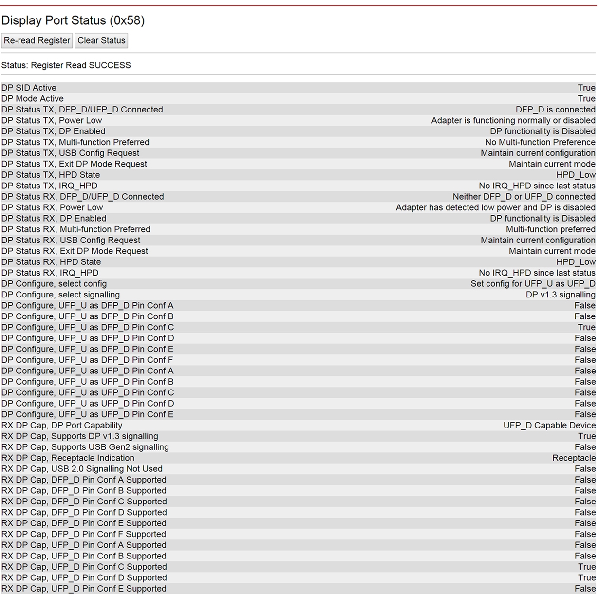
    Attached is a screengrab of the DisplayPort Status register. I have measured the HPD pin and it is indeed high (3.3V).

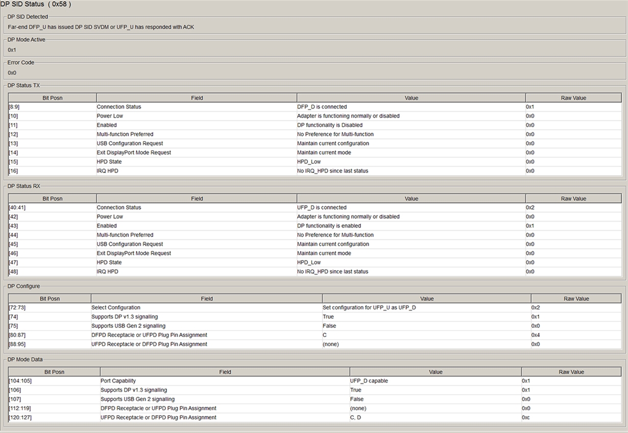
  • I should mention that this is the status register of the TPS65986 on my source board.
  • Hi Matt,

    That clears things up. My suggestion is completely from the DisplayPort point of view for the source  board connected to the notebook DisplayPort source. Check the attached diagram. The source board DisplayPort receptacle is connected as a UFP to the DisplayPort source from the notebook.  For the Type-C PD point of view your board will be a DFP_D as it is a source of DisplayPort. We would have to see how your DisplayPort connector from your board is connected. As DisplayPort connectors can be connect as DFP or UFP you have to go by the pin number and not the labels like ML0-3 (some vendors put the DFP/UFP version in their pinouts).

    Could you try using the latest tool and run the debug mode option? That older tool may not have the latest mapping.

    Jacob

    dp_example.pdf

  • Jacob,

    Thanks for the explanation. The diagram helps. So the ultimate DisplayPort source is a COM Express computer which interfaces to my board through a ribbon cable and from that I my board gets the four DP pairs (called DP_PAIR0, DP_PAIR1,DP_PAIR2, DP_PAIR3) along with AUX and other DP signals. Note that from here if I were to wire up these pairs to a standard DisplayPort receptable (wiring D_PAIR0 to ML_LANE 0, D_PAIR1 to ML_LANE... pinout for the connector shown on the wikipedia page for DisplayPort ) the link works just fine and my monitor displays data.

    I downloaded the latest tool and was able to grab the DP status register contents (From my board, the DFP_D). See below.

    Interesting that DP is shown as Disabled at both ends..

  • Hi Matt,

    It looks like you are connected. The DP configure is set so that indicates that we enter DP alternate mode but also set the appropriate pin assignment. There could be some parsing errors as some bit fields look weird.

    Could you check out Data Status (0x5F)? I want to confirm we have the same register read.

    Jacob

  • Jacob,

    I tried a number of things today to no avail. Eventually I tried loading the EVM firmware onto my board and then hard tying GPIO1 to 3.3V so that the switch in the first position of the mode switch was ON (sets the CFC ID to 1). This is the configuration that the source board is in when both EVMs are successfully talking to eachother and DP is working. I didn't get video when I tried this. This is further confirmation to me that there's a hardware issue, not some configuration issue.

    I'm still not sure how to go about figuring out if I miswired the DP lanes however.. As I just have lanes 0 through 3 as inputs to my board straight from a CPU module..
  • Hi Jacob,

    Attached is the Data Status register for my device (currently programmed with the EVM firmware with CFG_ID set to 1 so it thinks it's a DFP_D.

    Also I understand your explanation how DP works now in that every cable is actually a crossover cable. So the effect is that every DP receptacle needs to be wired appropriately based on if it's a source or a sink. And from a high level, source ports need to be connected to sink ports. Since the connection to my board comes over a ribbon cable there is no swapping/swapping back so I believe my DisplayPort lanes are wired correctly.

  • I've also suspected loss through the ribbon cable which attaches the CPU module (the source of the DP signals) to my board. I've done away with the cable so the boards are now directly connected and I still don't get video. I've also made efforts to shorten my USB C-C cable down to ~6in and I have a .5m mini DisplayPort to DisplayPort cable running from the EVM to the monitor.. I don't quite have the instrumentation yet to measure the DisplayPort signals directly..
  • Hi Matt,

    Did you get this working? The other thing I can think of are AUXN/P pull-up and pull down. AUX_N should have a pull up and AUX_P should have a pull down.

    Jacob
  • Hi Jacob,

    No, I haven't gotten this working yet. Still stuck. The AUXN/P pulls should be on the J1/J2 pins (AUX_P/AUX_N)? The EVM board has DNP pulls on C_SBU1/C_SBU2..
  • Hi Matt,

    They are not placed on the EVM because they would be on the Notebook DispalyPort source and Monitor. If we were to add the pull-up and pull-downs we would have a double pull-up and pull-down on the AUX_P/N. In a DIsplayPort source system you will have to place these pull-up/down since you are connected the DisplayPort source directly to the SS Mux and Type-C connector. Some DisplayPort monitors require the divider on AUX_N/P in order to set HPD.

    The weak pull-downs on SBU 1/2 are options are a back up option to support the minimum pull down resistance on SBU 1/2 in the Type-C specification.

    Jacob
  • Jacob,

    I can scope the AUX signals and it looks like they are properly pulled to ~3V (AUX_N) and GND (AUX_P). I see some data bursts on top of those DC biases. I think I have this right as I can get the system working with the 2 EVMs, both of which do not have these additional pull up/ pull downs...
  • Hi Matt,

    You still need these. They are not present on the EVM but they are still in the system with the two EVMs.

    You should get a voltage divider on AUX_N/P.

    Jacob

  • Hi Jacob,

    Finally got this working. Indeed I had the DP pairs hooked up with the wrong polarity to the mux. Thanks for the help.

    Lastly I have a question about HRESET. On the eval board the HRESET pin gets tied to just about 3V when you hit the reset button. However the datasheet says that HRESET cannot exceed .3V above 1.8V. Which is correct?

    Thanks again for the help.

  • Hi Matt,

    Glad to hear you were able to get the board working.

    For HRESET it's max voltage should be 1.8V. This is a mistake we made on the 982EVM. It may not hurt the device when asserted for short amounts of time but we do not recommend doing this.

    Jacob