This thread has been locked.

If you have a related question, please click the "Ask a related question" button in the top right corner. The newly created question will be automatically linked to this question.

SN65HVD73: SN65HVD7x input resistor for increased voltage swing

Part Number: SN65HVD73

Hello TI,


Similar to this thread:

http://e2e.ti.com/support/interface/f/138/t/353743

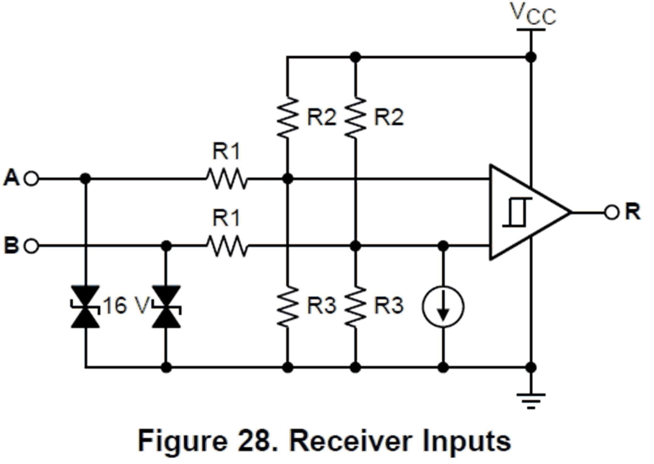
we wish to extend the SE input swing of the SN65HVD7x buffer to be RS-232 swing compatible: ±25V if possible, or at least ±15V, per input pin, each input pin independent of the other, if possible.

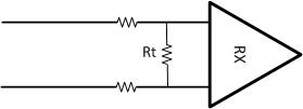
Would it be possible to achieve this by adding a series resistor (or series resistor plus clamp) between the receiver-side RS-422 termination and the input pins of the SN65HVD7x, and what would the recommended maximum resistor value be for reliable RS-422 operation?

  • Bernhard,

    I draw a simple diagram for your reference.

    I think the idea would work but you may need to pay attention for some details. 1) by adding the series resistor, you change the termination therefore you may see some reflection in the signal; 2) SN65HVD73 RX has the abs max -13V to 16.5V, which is pretty close to ±15V (RS-232's operation range). ±25V is the abs max of RS-232's signal; 3) By adding a resistor divider, you change the input voltage of RX. Please be sure that Vid is larger than the threshold of the receiver to make the communication work. Please let me know if you have more questions.

    Regards,

    Hao

  • Hello Hao,

    We were thinking more in this direction:

    Rt is the standard termination value. What is the largest value of Rs which will ensure compliant RS-422 and RS-485 reception and what is the largest corresponding RS-232 swing which will not damage the SN65HVD7x?

    Or please supply the values and tolerances of R1, R2, R3, I_current_source, and ±V_detect_diff(min) in the equivalent input diagram of the SN65HVD7x below, so that we can calculate this.

  • Bernhard,

    R1=175kOhm, R2=16kOhm, R3=20kOhm. I current is about 1uA and Vit of the comparator is about 40mV. But I don't recommend design a resistor divider based on these parameters, which are typical values and only meant for reference (this is an equivalent schematic). The real values could be different. Please let me know if you have more questions.

    Regards,
    Hao