Part Number: DP83822H
Other Parts Discussed in Thread: AM4376,
- Using the DP83822H PHY in design together with AM4376 as MAC
- Issue seems to be temperature dependent (occurrence increase with temperature). Testing at Ta = +70°C, Tc at DP83822H is <90°C
- First assumption of sporadically unintended strapping information (because of temperature, input leakage etc.) at power up could not be confirmed yet (readout of strapping registers after power up was consistent and not different in case of missing link.
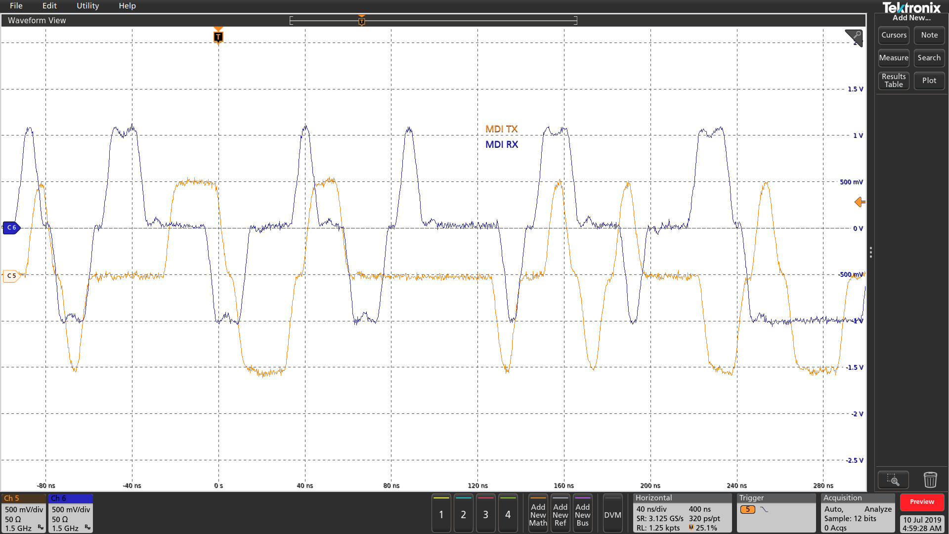
- Scope plot below showing boot timing at Ta = 25°C. MII2_COL was used to monitor, because strapping level affects PHY Adress Bit 0 and PHY mode (mode 2 and 3 = FX_EN, fiber mode)
- At power up, MII2_COL pulled up internal. About 200ms later, the /POWER_RES is released, starting the MAC to boot (1st stage, MII2_COL at <2V and 2nd stage, MII2_COL with internal PU at <3,3V)
- Reason for MII2_COL beeing ~200mV below VDD should be voltage drop from input leakage and internal PU, but level well within intended strapping mode 4 (2,29V..3,3V). There is no external PU/PD resistor at MII2_COL.
- At the end of the 2nd boot stage, the PHY reset is released (light blue) and the PHY is changing into operating mode, driving the MII2_COL low.
- Not shown (but verified), the first MDIO access starts not before <200ms after PHY reset release (MDC starting 200,1ms after reset)
- From the timing diagrams in the datasheet it is not clear, which diagram applies to the presented startup phase and at what point in time the strapping pins are latched

- The datasheet (section 8.5.1) is showing: "the values of these pins are sampled at powr up or harware reset" and there are two diagrams shown (Figure 1, Power-Up timing and Figure 2, Reset Timing)
- In both diagrams, the PHY clock is already active before the power supply ramp up ???.
- In the Power-Up diagram (Figure 1), the reset is released at the same time of the supply ramp up, which is different to the bootsequence presented above. Which timing diagram would apply here ???
- T2 = max. 200ms after reset release, the post power up stabilization time after reset release before MDC is kept (not shown here, but verified)
- T3 = typ. 200ms hardware configuration latch-in time for power up after reset release can't be valid here, because the PHY is actively driving the MII2_COL low already at this time. This means the latch in must have been before, but where ???
- T4 = typ. 64ns after the latch-in, the output drivers are getting active, driving the MII2_COL low. That also shows that the latch in can't be 200ms after reset release in the presented sequence