This thread has been locked.

If you have a related question, please click the "Ask a related question" button in the top right corner. The newly created question will be automatically linked to this question.

SN65HVD72: SN65HVD72D : Auto Transreceiver through single GPIO

Part Number: SN65HVD72
Other Parts Discussed in Thread: TIDA-01090

Hello TI Team 

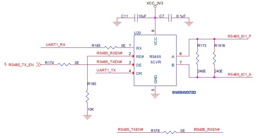
Currently we are using SN65HVD72D chipset, and controlling its DE and RE pin through single GPIO. Have a look at the attachment. 

By making GPIO either high/low we are enabling its Driver/receiver manually, its working fine in this condition. Now we want to operate this chipset in auto transreceiver mode as it should work. Please suggest how can we configure this chipset from SW side or we need to do some updation from HW side. 

  • Hello Gagandeep,

    There are a few different ways to accomplish this. I'm not in the office today, but when I am back on Monday I can send you some example implementations.

    Regards,

    Max

  • Gagandeep,

    The simplest solution would be to place a pull-up resistor on the "A" line, a pull-down resistor on the "B" line, tie the "D" input low, and then provide your data signal to the "DE" input instead.  This way there would be a couple of different output states:

     - When the input data line is high, the transceiver output is driven to a differential low level
     - When the input data line is low, the transceiver output is disabled and the differential bus is biased high via the external resistances.

    This approach has a few drawbacks.  One is that it requires the input data to be inverted in order to match the standard RS-485 signal polarity (which uses a high level in the idle state in most applications).  Another is that the transition time from low to high is dependent on the external resistance values used and the load capacitance of the network - in some cases this could mean that the transition is too slow for a given application.  Another issue is that the high level is not driven via a low-impedance output and thus its amplitude will not fully comply with RS-485 standard requirements for standard load conditions.

    Some additional circuits can be used to help to address these concerns:

    The FET here helps to invert the signal so that a low level on the data input (here marked “TX”) results in a low level on the RS-485 bus and vice-versa for high levels. The R/C/diode circuitry on the gate of the FET can be used to help speed up the transition from low to high states. When the TX line goes high, it takes some time to charge up the gate capacitance of the FET. During this period, the DE pin remains high and the driver remains enabled. The amount of time the driver remains enabled will depend on the R/C values chosen, and depending on application needs could be shorter or longer than the time required for a single bit. During this time, the transmitter output will meet the requirements defined in the RS-485 standard for a high state.

    It is also possible to use a logic circuit to assert the “DE” line for a fixed duration upon a falling edge of the “D” signal. This approach is shown in the reference design TIDA-01090:

    http://www.ti.com/tool/TIDA-01090

    This is useful if the length of each data frame is fixed to a known value since it allows each transmitter to remain active for a predictable amount of time when sending data.

    I hope this is all clear; please let me know if you have further questions.

    Regards,
    Max

  • Hello Max Robertson

    Thanks for the suggestion.

    I have just one query, Is half duplex RS485  standard comes with a, manually Driver/Receiver Solution ? Is there any IC that has inbuilt auto trans receiver solution ? . 

  • Hello,

    Yes, standard half-duplex RS-485 implementations would require driver/receiver enable controls in order to control the direction of data flow on a bus (so that multiple drivers are not enabled simultaneously).  TI does not offer a transceiver with automatic direction control at this time.  The discrete solution shown above can be used, though, and gives some flexibility in the duration that the driver circuit becomes enabled in response to data toggling on the D input.

    Regards,
    Max