Other Parts Discussed in Thread: TMDS181, SN75DP159
Dear David,
I have the same question as Sjoerd (intra- and interpair skew TMDS181) about the inter and intra-pair skew but now for the SN75DP159RGZ. We design a PCB with one HDMI input (for the connection to a camera) and one HDMI output (for a connection to a monitor). The HDMI output uses a SN75DP159 (output of the SN75DP159 is connected to the HDMI connector) and the HDMI input a TMDS181 (input of the TMDS181 is connected to the HDMI connector). The output of the SN75DP159 is connected by PCB traces to a HDMI connector. The input of the TMDS181 is connected by PCB traces to HDMI connector. For the PCB traces I have to know the inter- and intra pair skew.
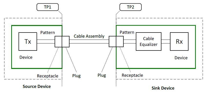
The HDMI spec defines for the source at TP1 (at HDMI connector) the following skew values
| Parameter | TTP1 (HDMI2.0) | TTP3(SN75DP159RGZ) | Margin (left over for the PCB between TTP1 and TTP3) |
| Intrapair skew tolerance | 0.15Tbit | 0.15Tbit | 0 |
| Interpair skew tolerance | 0.2Tcharacter | 0.2Tcharacter | 0 |
Remark: in the datasheet of the SN75DP159 is not defined on which points the intra- and inter-pair skew iss measured but it is assumed that the values in the datasheet are measured on the TMDS data/clock pin of the chip (TTP3). Please confirm if this is correct.
If above is correct that I don't have any margin for the PCB traces. Please can you give me the inter- and intra-pair skew for my PCB traces between the output of the SN75DP159 and HDMI connector?
Figure 2: testpoints according HDMI spec
I have the same question as described above but now for the inter- and intra-pair skew of the PCB traces between the HDMI connector and the input of the TMDS181.
| Parameter | TTP2 (HDMI2.0) | TTP2 (TMDS181) | Margin (left over for the PCB between TTP2 and TTP2) |
| Intrapair skew tolerance | 0.15Tbit+112ps | 0.15Tbit+112ps (for 3.4G < Rbit < 6.0G) | 0 |
| Interpair skew tolerance | 0.2Tcharacter+1.78ns | 0.2Tcharacter+1.78ns | 0 |
Thanks and in advance,
Marcel


