This thread has been locked.

If you have a related question, please click the "Ask a related question" button in the top right corner. The newly created question will be automatically linked to this question.

TFP410: No video on external HDMI monitor

Part Number: TFP410
Other Parts Discussed in Thread: MSP430G2230

This is an extension to the project found in this thread:

https://e2e.ti.com/support/interface/f/138/p/851103/3151025#3151025

You can find my schematic and code in the above link.

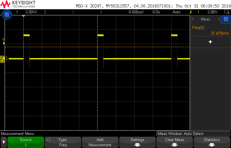
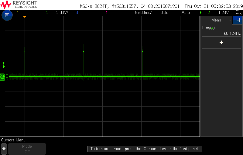
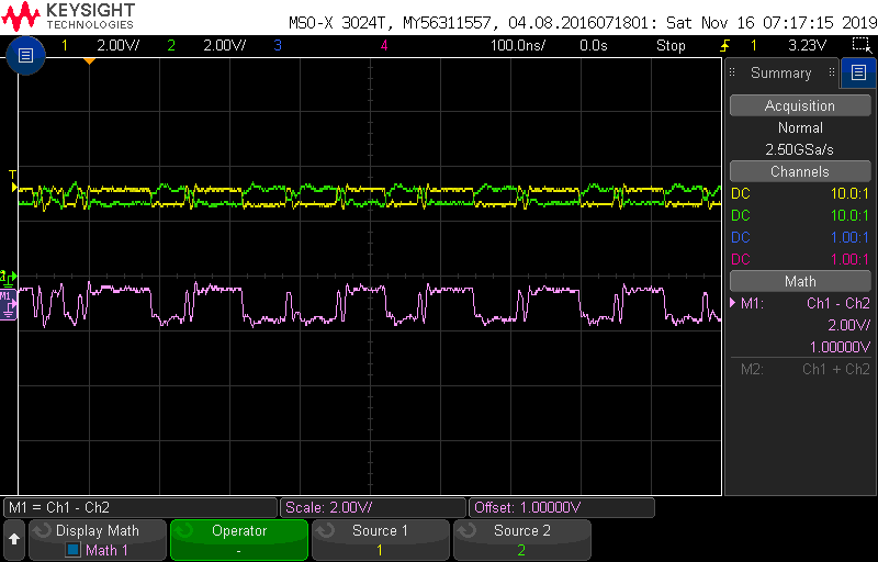
The issue I am having now is that there is no video output to my HDMI monitor. When I plug and unplug my HDMI cable the monitor responds with a message saying "No HDMI Signal", which only appears when the cable is connected or removed. Thus I believe my HPD is working properly - it is at least detecting that it is being plugged in. 

I.K. in the above thread suggested it may be a problem with my DE signal, which I am generating with my code. Based on the provided schematic and C files, is it possible to determine what the cause of this "No Signal" error is?

A bit of background: I am modifying an old existing design to produce an HDMI output. The original design used 8-bit R, G, and B signals which were fed into an Analog Devices ADV7125 chip, which produced an 800x480 VGA output. I replaced the ADV7125 with the TFP410 since it could also accept 8-bit R, G, and B signals as inputs, but produced an HDMI output instead of VGA (my newer monitors don't have a VGA port). The DE values, along with the other specs, are based on the VGA device and I am not entirely sure whether or not they need to change when switching to an HDMI transmitter.

Thank you,
Isaiah Washburn

  • Hi Isaiah,

    Can you check the below items? 

    1. Do you see the input/output clock on an oscilloscope? Is it the correct frequency/amplitude?

    2. Do the HYSNC/VSYNC signals look correct? I would ask about DE too but I'm not sure if you would be able to look at this signal since it's internally generated.

    3. Can you review section 7.4.3 of the datasheet in regards to HTPLG, MSEN, and RSEN?

    4. What is the state of the PD# bit in the CTL_1_MODE register?

    5. The TFP410 requires a reset after power up. Instead of pulling ISEL/RST#, can you tie it to your system reset (see section 7.4.4)?

    Regards,

    I.K.    

  • Hello I.K.,

    I.K. Anyiam said:

    1. Do you see the input/output clock on an oscilloscope? Is it the correct frequency/amplitude?

    The input clock is measuring 40MHz, as expected (channel 1, yellow). The output TMDS CLK+ is a very ripply 3.3V (channel 2, green).

    2. Do the HYSNC/VSYNC signals look correct? I would ask about DE too but I'm not sure if you would be able to look at this signal since it's internally generated.

    HSYNC and VSYNC look correct. HSYNC is measuring 37.88kHz and VSYNC is measuring 60.12Hz, which is consistent with the 800x600p driver (implemented with a FPGA).

    3. Can you review section 7.4.3 of the datasheet in regards to HTPLG, MSEN, and RSEN?

    According to section 7.4.3:

    "When I2C is enabled, the connection status of the DVI link and HTPLG sense pins are provided by the CTL_2_MODE register"

    My HTPLG (HPD) pin is connected directly to Pin #19 of the HDMI connector. MSEN is pulled high through a 4.53k resistor, and outputs the HTPLG bit in the firmware (lines 49 and 50 in main.c - ignore the comment saying it's disabled, that is not accurate). I'm not exactly sure what I should be doing with these pins/bits/values.

    4. What is the state of the PD# bit in the CTL_1_MODE register?

    PD# is set to 1 (Normal operation) in lines 46 and 47 of main.c.

    5. The TFP410 requires a reset after power up. Instead of pulling ISEL/RST#, can you tie it to your system reset (see section 7.4.4)?

    Unfortunately I do not have a system reset. Currently the micro switches on at the same time as the TFP410 (which is the same time the rest of the board powers up), and ISEL is simply connected to Vdd. Are you saying that this won't work properly? Do I need to cut the trace connecting ISEL to the supply (if I can even get to it) and connect it to one of the I/O pins on the micro instead, so that I can enable/disable it in firmware?

    Thank you,
    Isaiah Washburn

  • Hi Isaiah,

    Yes, please find a way to control ISEL. The TFP410 requires a reset after power up, so ISEL should be asserted high only after the power supplies are stable. 

    I remember another customer had a similar issue (no/bad video on the display intermittently), and they were also using the I2C to access the DE generator. Their ISEL pin was just connected to Vdd, but when they connected it to their system reset instead it fixed the issue.

    Can you also provide a register dump of the TFP410 so we can check if everything's being written correctly?

    Regards,

    I.K. 

  • I.K. Anyiam said:

    Hi Isaiah,

    Yes, please find a way to control ISEL. The TFP410 requires a reset after power up, so ISEL should be asserted high only after the power supplies are stable. 

    I remember another customer had a similar issue (no/bad video on the display intermittently), and they were also using the I2C to access the DE generator. Their ISEL pin was just connected to Vdd, but when they connected it to their system reset instead it fixed the issue.

    Can you also provide a register dump of the TFP410 so we can check if everything's being written correctly?

    Regards,

    I.K. 

    Hello I.K., thank you for your patience. I have been on vacation and just got back to this.

    I lifted the ISEL pin of the TFP410 and soldered a jumper wire onto it, which I then brought over to P1.2 of my MSP430G2230. I added in the following code:

    	// Configure I2C enable (ISEL) output
    	P1SEL |= BIT2;									// Select P1.2 to be I/O
    	P1DIR |= BIT2;									// Set P1.2 to output
    	P1OUT |= BIT2;									// Set P1.2 high
    
    	// Wait a bit for the power supplies to settle
    	__delay_cycles(50000);
    
    	// Reset I2C configuration registers
    	P1OUT &= ~BIT2;									// Disable I2C
    	__delay_cycles(10000);							        // Delay 10ms
    	P1OUT |= BIT2;									// Re-enable I2C
    
    	I2C_Init();										// Initialize I2C pins

    I added this code right before my I2C_init() function, after configuring the MSP430 clocks. I wasn't sure what to use for delays, so I guessed - 50ms to allow the power supplies to settle, and 10ms before re-enabling the I2C. Unfortunately this does not appear to have worked.

    You suggested I post a register dump of the TFP410. Would you be able to tell me how to do that? 

    Thank you,

    Isaiah W.

  • Hi Isaiah,

    For the register dump you'd just need to read back all of the TFP410 registers in the register map. 

    Also, taking another look at your clock waveforms, it looks like the input clock is around 6V in amplitude, which is over the absolute maximum rating listed in the datasheet. Can you reduce the amplitude to 3.3V so that it's within DC specifications? 

    Below are some additional items to check:

    1. Do you have access to the receiver in your monitors? If so can you look at the DE, HSYNC, VSYNC, and clock output of the receiver? We can see that these are available to the TFP410 on the input but they may not be getting transmitted to the receiver. 

    2. Can you check if there's any activity on the output TMDS data lanes of the TFP410? It looks like the output clock is pulled to 3.3V due to the termination on the receiver side, but it doesn't look like it's actually outputting a clock.

    Regards,

    I.K. 

  • I.K. Anyiam said:
    For the register dump you'd just need to read back all of the TFP410 registers in the register map.

    Oh of course, I should have known that. I'll give that a shot tomorrow, assuming I have time to work on this project.

    Also, taking another look at your clock waveforms, it looks like the input clock is around 6V in amplitude, which is over the absolute maximum rating listed in the datasheet. Can you reduce the amplitude to 3.3V so that it's within DC specifications?

    Good catch, I didn't even notice that! I just checked my schematic and I appear to be missing a 75 ohm resistor on the clock line that I imagine would have eliminated those peaks. You can see in the image the level at which the clock waveform is supposed to be. There are just large peaks before that level is reached. I will have to see if I can mod the existing board to put it in.

    Below are some additional items to check:

    1. Do you have access to the receiver in your monitors? If so can you look at the DE, HSYNC, VSYNC, and clock output of the receiver? We can see that these are available to the TFP410 on the input but they may not be getting transmitted to the receiver.

    Not that I am aware of, but I will have to dig into this once the existing, known issues have been corrected.

    2. Can you check if there's any activity on the output TMDS data lanes of the TFP410? It looks like the output clock is pulled to 3.3V due to the termination on the receiver side, but it doesn't look like it's actually outputting a clock.

    That was my instinct as well. Once again I can probe these pins once the known problems have been fixed.

    I will get back to you with additional information as soon as I get it.

    Thank you,
    Isaiah W.

  • Good day,

    I finally got to finish this round of testing this evening, so here are my results.

    I was able to cut a trace, scrape the solder mask off of both sides, and solder in a 100 ohm resistor between the FPGA output and the TFP410 clock input pin. I would have used 75 ohms but did not have any resistors with that value handy. This cleaned up the clock signal substantially:

    My next step was to read back the I2C registers after (supposedly) writing to them. The write of one of the registers is shown below - all appears to be in order:

    To read back the data, I added the following line of code just below the I2C_WriteData() call and the subsequent 1ms delay:

    I2C_ReadData(Buff, SLV_ADDR, CTL_2_MODE, 1);
    

    Unfortunately, the results do not look good:

    As you can see, it is reading back 0x00 when it should be reading back 0x39. Below is my I2C_ReadData() function contents:

    /*--------------------------------------------------------------------------------
    Function    : I2C_ReadData
    Purpose     : Read n bytes from I2C bus
    Parameters  : Buff          - Pointer to buffer for storing value
                  DevideAddr    - Device Address
                  Register      - Register Address
                  nLength       - Number of bytes to be read
    Return      : None
    --------------------------------------------------------------------------------*/
    void I2C_ReadData(unsigned char *Buff, unsigned char DeviceAddr, unsigned char Register, unsigned char nLength)
    {
        unsigned char nIndex;
        I2C_Start();
        I2C_WriteByte(DeviceAddr << 1);
        I2C_WriteByte(Register);
        I2C_Stop();
        _NOP();                                 // Short delay
        I2C_Start();
        _NOP();                                 // Short delay
        I2C_WriteByte((DeviceAddr << 1) | 1);
        for(nIndex = 0; nIndex < nLength; nIndex++)
        {
            *(Buff + nIndex) = I2C_ReadByte();
                if(nIndex > 0)I2C_Writebit(ACK);
        }
        I2C_Writebit(NACK);
        I2C_Stop();
    }

    I tried increasing the delays after I2C_Stop() and I2C_Start() but that did not seem to have any effect. Since I am apparently not properly configuring the registers, I suspect that is why I am not seeing any clock on the TMDS side of things. 

    I do not seem to have access to the receivers in the monitors, unfortunately. 

    What might cause the config data to not be properly written to the TFP410, even though I am still receiving ACKs?

    Thank you,
    Isaiah W.

  • Hm that’s interesting. It seems like your write/read process are correct, so I’m not sure what could be causing this other than the register somehow getting reset before you read it (the default is 0x00).

    I’ll see if I can recreate this in the lab.

    Regards,

    I.K.

  • I.K. Anyiam said:

    Hm that’s interesting. It seems like your write/read process are correct, so I’m not sure what could be causing this other than the register somehow getting reset before you read it (the default is 0x00).

    I’ll see if I can recreate this in the lab.

    Regards,

    I.K.

    Hello I.K.,

    Thank you very much for your continued support. Have you been able to reproduce this issue?

    Best,
    Isaiah W.

  • Hi Isaiah,

    Sorry for the delay. Unfortunately I have not been able to locate a board for this device. It seems lab work for this device has not been done for quite some time.

    In parallel, I took another look at your I2C write waveform and noticed something strange.  

    Unless I counted incorrectly it looks like there's an extra pulse on SCL at the end of the operation (I marked the ACK cycles with red).

    Additionally, it looks like there are some quick pulses on SDA after every ACK bit but before the start of the next byte. Do you know what the source of these pulses are? I can't really tell where they are in relation to SCL, but I wonder if they could be erroneously triggering START/STOP conditions.

    Also, is register 0x09 the only register that is returning all 0? For example, can you read register 0x00 (VEN_ID)? This register should return 0x4C. 

    Regards,

    I.K. 

  • Hello I.K., thank you for the response.

    I attempted to read Address 0x00 by running this line of code immediately following the I2C_Init() call and restarting the I2C bus:

    I2C_ReadData(Buff, SLV_ADDR, 0x00, 1);

    This also returned 0x00:

    Good catch on the extra SCL clock pulse during the write operation though. I'll have to review my code to see if I can figure out where that came from. I will try that tomorrow. Regardless, I wouldn't expect that to have an effect on the above test. I do that before I write anything, and that register (0x00 - VEN_ID) is read-only.

    All of the registers appear to be returning 0x00.

    Thanks,
    Isaiah W.

    UPDATE: I decided to do one more sweep of the code tonight to see if I could track down that extra SCL pulse and I found what was causing it. Simple fix, so that is no longer an issue:

    I still have the same issue reading the register back though.

  • Hi Isaiah,

    Just noticed something in the datasheet: 

    It might be that the device is in powerdown mode, since this is the default state after a reset:

    This may be why every register you read returns 0. Can you try writing a 1 to bit 0 in register 0x08 right after your reset?

    Regards,

    I.K. 

  • I.K. Anyiam said:

    Hi Isaiah,

    Just noticed something in the datasheet: 

    It might be that the device is in powerdown mode, since this is the default state after a reset:

    This may be why every register you read returns 0. Can you try writing a 1 to bit 0 in register 0x08 right after your reset?

    Regards,

    I.K. 

    This might explain why my check for VEN_ID doesn't work, but it does not explain why nothing else works. The first command I send over I2C after the reset is this:

    /* Configure TFP410 Digital Transmitter */
     
    // 0x37, T.M.D.S. enable state determined by PD
    sData = 0x37;
    I2C_WriteData(&sData, SLV_ADDR, CTL_1_MODE, 1);

    0x37 writes a 1 to the #PD bit. Also, #PD is only for the TMDS outputs, is it not? The I2C module should still be running, otherwise you would never be able to configure the TFP410 over the bus. I would expect to still be able to read fixed I2C registers even if the TFP410 is in power-down mode. Am I wrong here?

  • Hi Isaiah,

    True, I believe you're correct. I'm not sure what could be causing this other than the device being in some sort of a power-down state. Your I2C read process is also exactly what the datasheet specifies so it's very strange that every register is returning 0. Here is an additional experiment to try if you have the option:

    Let's ignore I2C for now and see if we can get a valid clock output in pin-strap mode. You won't see anything on the display due to the absence of a DE signal, but I think if we can do this and see a valid clock output then it would point to the root cause having something to do with the I2C interface. 

    For this you'd need to make the following modifications:

    1. Keep ISEL low (tie to ground)

    2. PD# should be tied high instead of tied to ground

    Regards,

    I.K. 

  • I.K. Anyiam said:

    Hi Isaiah,

    True, I believe you're correct. I'm not sure what could be causing this other than the device being in some sort of a power-down state. Your I2C read process is also exactly what the datasheet specifies so it's very strange that every register is returning 0. Here is an additional experiment to try if you have the option:

    Let's ignore I2C for now and see if we can get a valid clock output in pin-strap mode. You won't see anything on the display due to the absence of a DE signal, but I think if we can do this and see a valid clock output then it would point to the root cause having something to do with the I2C interface. 

    For this you'd need to make the following modifications:

    1. Keep ISEL low (tie to ground)

    2. PD# should be tied high instead of tied to ground

    Regards,

    I.K. 

    Okay, I see where you're going. Modding the board to pull #PD high will be tricky, as the connection to ground is made beneath the chip. I'll have to lift the pin, and from past experience (when lifting the ISEL pin) these pins are extremely fragile. I'll see if I can do that tomorrow.

    Thank you,
    Isaiah W.

  • Hello I.K.,

    I was able to tie ISEL low and #PD high, and plug the board into my system. Probing the clock lines, this is what I see:

    It looks like there is somewhat of a clock there, but it seems a bit sloppy to me....

    Thank you

    UPDATE:
    It occurred to me that I am not probing the clock in the ideal fashion. I have a long ground clip on my probe, and long mod wires connecting to the clock + and - pins. Furthermore I am using the 1 Mohm input impedance. I suspect the discontinuities are causing reflections and are susceptible to noise, hence the odd-looking waveform. So it looks like I am getting an HDMI clock when running with the I2C disabled.

  • Hi Isaiah,

    Since you can get an output clock in pin strap mode, this means that there's something amiss with the I2C. For now the only thing I can think of is that the device is in some sort of power down state, but this doesn't explain why every register you read is returning 0.

    Although, if something is wrong with the I2C read then maybe there is also something wrong with the I2C write. If this is the case and the TFP410 is not correctly recognizing your register writes, then the device would be in power-down mode since you have to successfully write to register 0x08 to take it out of power-down. 

    We've had other customers successfully  use the I2C interface so I don't think it's an issue with the device itself, but I'll need to discuss this with my team and see what exactly could be the issue here. 

    Regards,

    I.K. 

  • I have made some progress! I moved ISEL back to P1.2 of the micro and #PD back to ground, and modified my I2C code. The issue was that I had an extra stop during the read function, creating an I2C restart instead of an I2C repeated start. I was able to bit-bang a proper repeated start condition and now the data is reading correctly, both from the read-only registers and the ones that I write to:

    I do appear to be generating a clock output on the HDMI connector, though due to my poor probing technique (proper probing with this board in the system is extremely difficult) it looks very sloppy. I suspect if I had very short ground leads on my probes and was monitoring the pins directly, it would be much cleaner. 

    Unfortunately I am still not getting any video output. Any further ideas?

    Thank you very much for your continued support.

    Best,
    Isaiah W.

  • Hi Isaiah,

    Great news that you got the I2C working properly. Can you provide a register dump of the TFP410 now so that we can ensure that all the registers have been written correctly?

    Regards,

    I.K. 

  • I.K. Anyiam said:

    Hi Isaiah,

    Great news that you got the I2C working properly. Can you provide a register dump of the TFP410 now so that we can ensure that all the registers have been written correctly?

    Regards,

    I.K. 

    Here are the registers/values, minus the ones that are "Reserved"

    Register Register Name Data Type Value
    0x08 CTL_1_MODE unsigned char 0x37
    0x09 CTL_2_MODE unsigned char 0xBC
    0x0A CTL_3_MODE unsigned char 0x80
    0x0B CFG unsigned char 0x24
    0x32 DE_DLY unsigned char 0xD8
    0x33 DE_CTL unsigned char 0x70
    0x34 DE_TOP unsigned char 0x1B
    0x36 DE_CNT_L unsigned char 0x20
    0x37 DE_CNT_H unsigned char 0x03
    0x38 DE_LIN_L unsigned char 0xE0
    0x39 DE_LIN_H unsigned char 0x01
    0x3A H_RES_L unsigned char 0x08
    0x3B H_RES_H unsigned char 0x00
    0x3C V_RES_L unsigned char 0x0B
    0x3D V_RES_H unsigned char 0x00

    I noticed that Address 0x09 (CTL_2_MODE) is showing a value of 0xBC instead of 0x39 like I'm writing to it:

    	sData = 0x39;
    	I2C_WriteData(&sData, SLV_ADDR, CTL_2_MODE, 1);

    However, VLOW (Bit 7) and RSEN (Bit 2) are read-only, so those differences in CTL_2_MODE make sense. MDI (Bit 0) is the monitor detect interrupt mode, so I expect that to vary depending on whether or not a monitor is plugged in. That also seems logical, so all of the registers match what I expected. Perhaps I determined the value of one incorrectly?

    Thank you,
    Isaiah W.

  • Hi Isaiah,

    Can you double check your timing requirements for DE? 

    From your register values we have:

    • DE_DLY = 216
    • DE_TOP = 27
    • DE_CNT = 800
    • DE_LIN = 480

    However, the values for H_RES and V_RES from the register dump do not make sense:  

    • H_RES = 8
    • V_RES = 11

    These are read-only registers, and should reflect the total horizontal and vertical pixels that the TFP410 receives. This could also mean that your video source is not outputting the correct resolution properly. 

    Regards,

    I.K. 

  • I.K. Anyiam said:

    Hi Isaiah,

    Can you double check your timing requirements for DE? 

    From your register values we have:

    • DE_DLY = 216
    • DE_TOP = 27
    • DE_CNT = 800
    • DE_LIN = 480

    This is interesting. The values I came up with that I needed are as follows:

    • DE_CNT= 800px
    • DE_LIN = 600px
    • DE_DLY = 216px
    • DE_TOP = 27px

    Perhaps I never updated the settings for DE_LIN after determining this?

    However, the values for H_RES and V_RES from the register dump do not make sense:  
    • H_RES = 8
    • V_RES = 11

    These are read-only registers, and should reflect the total horizontal and vertical pixels that the TFP410 receives. This could also mean that your video source is not outputting the correct resolution properly.

    How is this information conveyed from the monitor to the controller, exactly? Does it use the I2C bus? Remember I pulled off the level shifter back when I was having issues with I2C. 

    I feel like we're getting closer!

    Thank you,
    Isaiah W.

    UPDATE:


    Here is the updated register dump after fixing DE_LIN:

    Register Register Name Data Type Value
    0x08 CTL_1_MODE unsigned char 0x37
    0x09 CTL_2_MODE unsigned char 0x3C
    0x0A CTL_3_MODE unsigned char 0x80
    0x0B CFG unsigned char 0x00
    0x32 DE_DLY unsigned char 0xD8
    0x33 DE_CTL unsigned char 0x70
    0x34 DE_TOP unsigned char 0x1B
    0x36 DE_CNT_L unsigned char 0x20
    0x37 DE_CNT_H unsigned char 0x03
    0x38 DE_LIN_L unsigned char 0x58
    0x39 DE_LIN_H unsigned char 0x02
    0x3A H_RES_L unsigned char 0x00
    0x3B H_RES_H unsigned char 0x00
    0x3C V_RES_L unsigned char 0x00
    0x3D V_RES_H unsigned char 0x00

    Still no info on the RES though, in fact that's completely blank. 

    My timing values come from this page: http://tinyvga.com/vga-timing/800x600@60Hz

  • Hi Isaiah,

    H_RES and V_RES are not determined by the monitor, they are determined by what the TFP410 receives on its input from the video source.

    The TFP410 counts the total number of HSYNC pulses between VSYNC pulses, and the total number of pixels between HSYNC pulses. For some reason it looks like the TFP410 is not seeing any HSYNC/VSYNC pulses. As a sanity check, are you certain that your video source is on and outputting data? The values you're seeing in H_RES and V_RES are very strange. I'd expect H_RES to be 1056 and V_RES to be 628 based on your timing above. 

    Additionally, since you're using the DE generator, you need to make sure that timing matches your source, not your monitor. Can you double check that your source is outputting the SVGA signal parameters you listed (in your original post you mentioned 800x480)? 

    Regards,

    I.K. 

  • Well, it appears I've been wasting your time since we got the I2C working properly. I re-inspected my PCB, which I had done many, many times before mind you, and using a 10x eye loupe I discovered there were a few solder bridges beneath the edges of the IC. Well, a few might be an understatement. Almost one entire side of the TFP410 was shorted together! The bridges were very difficult to see, but they were definitely there! That's what you get for assembling a densely-packed board yourself with a spool of solder and a soldering iron! After a couple of hours I managed to clear the solder bridges and sure enough, it fired right up! The image has a bit of a green tinge, so I may not have fully cleared all of the solder bridges, but at least I have an image! 

    You have been immensely helpful over these past weeks, and I greatly appreciate your efforts!

    Many thanks,
    Isaiah W.

  • Hi Isaiah,

    Great news that you found the issue! I had been wondering why the "VLOW" field flipped from 0 to 1 in the different register dumps you provided, since it's a read-only register that reflects the state of the Vref pin. Perhaps that was due to the solder bridges. Hopefully now you'll be able to get a clear image after cleaning up your board some more. 

    Regards,

    I.K.