Other Parts Discussed in Thread: MSP430G2230
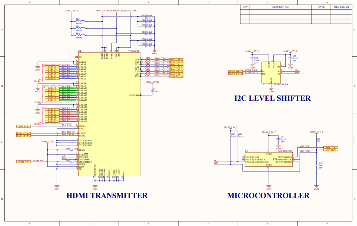
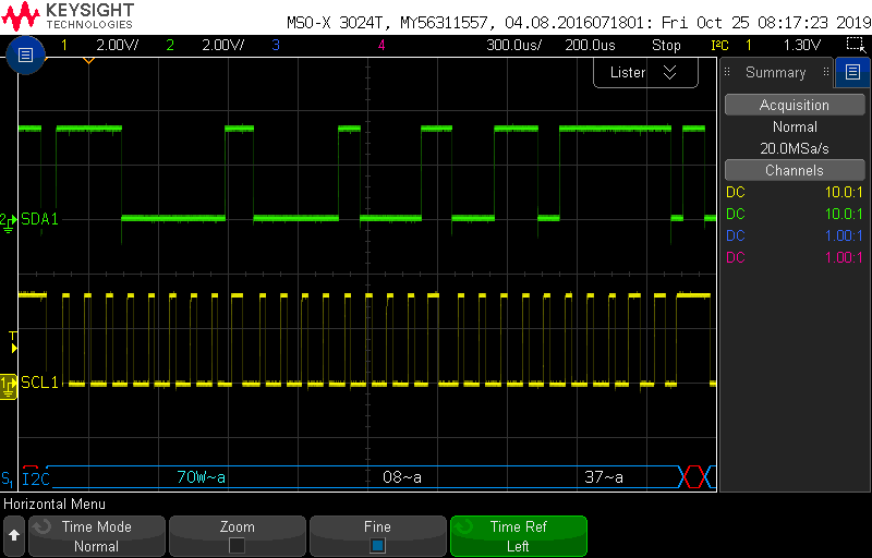
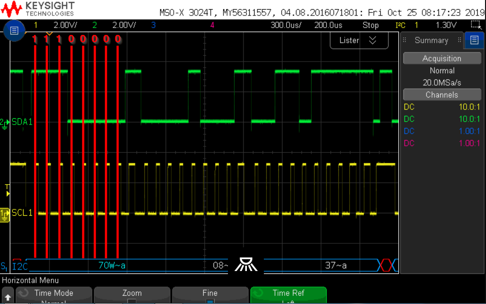
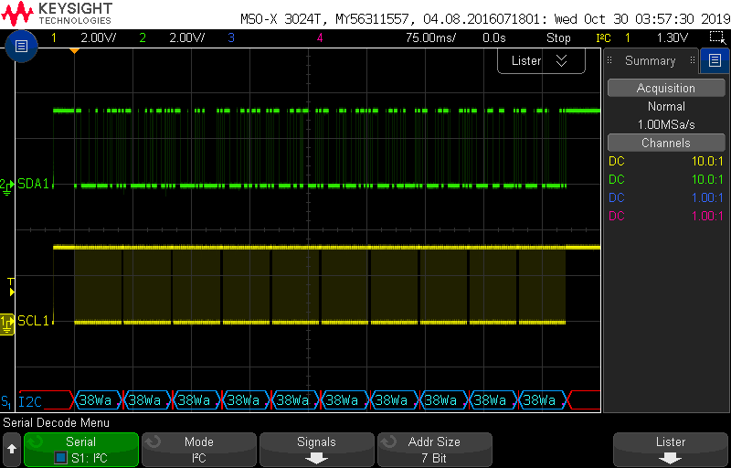
I am using the TFP410 to interface with an external HDMI monitor, set to be configured on power-up by an MSP430G2230 micro via the I2C connection (see schematic snippet). The issue I am currently having is that the TFP410 does not ACK any of the commands (see scope screenshot). My SCL is running at approximately 11kHz and I am bit-banging the I2C pins. My code is as follows:
main.c:
/*
 * main.c
 *
 *  Created on: Sep 26, 2019
 *
 */

#include <msp430.h>
#include <i2c_sw.h>

/* Sub-Addresses for the TFP410 */
#define CTL_1_MODE 0x08
#define CTL_2_MODE 0x09
#define CTL_3_MODE 0x0A
#define DE_DLY 0x32
#define DE_CTL 0x33
#define DE_TOP 0x34
#define DE_CNT_L 0x36
#define DE_CNT_H 0x37
#define DE_LIN_L 0x38
#define DE_LIN_H 0x39

#define SLV_ADDR 0x70                               // Write address

unsigned char sData = 0;                            //Data to be written to slave

int main(void) {

    WDTCTL = WDTPW | WDTHOLD;                       // Stop watchdog

    /* Initialize clocks */
    BCSCTL3 |= LFXT1S_2;                            // Select VLO as low freq clock
    if (CALBC1_1MHZ == 0xFF) {                      // If calibration constant erased
        while (1);                                  // do not load, trap CPU!!
    }
    DCOCTL = 0;                                     // Select lowest DCOx and MODx settings
    BCSCTL1 = CALBC1_1MHZ;                          // Set DCO
    DCOCTL = CALDCO_1MHZ;

    // Wait a bit for the FPGA to initialize
    __delay_cycles(10000);

    /* Configure TFP410 Digital Transmitter */

    // 0x37, T.M.D.S. enable state determined by PD
    sData = 0x37;
    I2C_WriteData(&sData, SLV_ADDR, CTL_1_MODE, 1);
    // 0x39, MSEN out disabled, MDI from HTPLG, MDI logic level stays same
    sData = 0x39;
    I2C_WriteData(&sData, SLV_ADDR, CTL_2_MODE, 1);
    // 0x80,sData de-skew disabled
    sData = 0x80;
    I2C_WriteData(&sData, SLV_ADDR, CTL_3_MODE, 1);
    // 0xD8, 216 pixels (HSYNC + back porch)
    sData = 0xD8;
    I2C_WriteData(&sData, SLV_ADDR, DE_DLY, 1);
    // 0x70, DE generator enabled, VSYNC & HSYNC active high
    sData = 0x70;
    I2C_WriteData(&sData, SLV_ADDR, DE_CTL, 1);
    // 0x1B, 27 pixels (VSYNC + back porch)
    sData = 0x1B;
    I2C_WriteData(&sData, SLV_ADDR, DE_TOP, 1);
    // 0x20, 0x03, 800 pixels wide
    sData = 0x20;
    I2C_WriteData(&sData, SLV_ADDR, DE_CNT_L, 1);
    sData = 0x03;
    I2C_WriteData(&sData, SLV_ADDR, DE_CNT_H, 1);
    // 0xE0, 0x01 480 lines tall
    sData = 0xE0;
    I2C_WriteData(&sData, SLV_ADDR, DE_LIN_L, 1);
    sData = 0x01;
    I2C_WriteData(&sData, SLV_ADDR, DE_LIN_H, 1);

    //__delay_cycles(10000);

    /* Trap after configuration */;
    while (1);

}
i2c_sw.c:
/*
 * i2c_sw.c
 *
 *  Created on: Oct 1, 2019
 *
 */

#include "msp430.h"
#include "i2c_sw.h"

unsigned char Read_SCL(void);
unsigned char Read_SDA(void);
void Clear_SCL(void);
void Clear_SDA(void);

void I2C_Init(void);
void I2C_Start(void);
void I2C_Stop(void);

void I2C_Writebit(unsigned char bit);
unsigned char I2C_ReadByte(void);

void I2C_WriteByte(unsigned char Data);
unsigned char I2C_ReadByte(void);

void I2C_WriteData(unsigned char *Data, unsigned char DeviceAddr, unsigned char Register, unsigned char nLength);
void I2C_ReadData(unsigned char *Buff, unsigned char DeviceAddr, unsigned char Register, unsigned char nLength);

/*--------------------------------------------------------------------------------
Function    : Read_SCL
Purpose     : Set SCL as input and return current Logic level of SCL (0 or 1)
              normal is 1 because it is pulled up by a resistor
Parameters  : None
Return      : Logic level of SCL pin
--------------------------------------------------------------------------------*/
unsigned char Read_SCL(void)
{
    I2C_PxDIR  &= ~SCL;
    return((I2C_PxIN & SCL) != 0);

}
/*--------------------------------------------------------------------------------
Function    : Read_SDA
Purpose     : Set SDA as input and return current Logic level of SDA (0 or 1),
              normal is 1 because it is pulled up by a resistor
Parameters  : None
Return      : Logic level of SDA pin
--------------------------------------------------------------------------------*/
unsigned char Read_SDA(void)
{
    I2C_PxDIR  &= ~SDA;
    return((I2C_PxIN & SDA) != 0);
}

/*--------------------------------------------------------------------------------
Function    : Clear_SCL
Purpose     : Set SCL as output, logic Low
Parameters  : None
Return      : None
--------------------------------------------------------------------------------*/
void Clear_SCL(void)
{
    I2C_PxDIR  |= SCL;
    I2C_PxOUT &= ~SCL;
}
/*--------------------------------------------------------------------------------
Function    : Clear_SDA
Purpose     : Set SDA as output, logic LOW
Parameters  : None
Return      : None
--------------------------------------------------------------------------------*/
void Clear_SDA(void)
{
    I2C_PxDIR  |= SDA;
    I2C_PxOUT &= ~SDA;
}
/*--------------------------------------------------------------------------------
Function    : I2C_Init
Purpose     : Initialize I2C block
Parameters  : None
Return      : None
--------------------------------------------------------------------------------*/
void I2C_Init(void)
{
    // Config SCL and SDA as GPIO
    I2C_PxSEL   &= ~(SCL + SDA);
    // Set SCL and SDA as input, pulled logic HIGH by resistors
    I2C_PxDIR   &= ~(SCL + SDA);
    I2C_PxOUT   &= ~(SCL + SDA);
}
/*--------------------------------------------------------------------------------
Function    : I2C_Start
Purpose     : Send start signal
Parameters  : None
Return      : None
--------------------------------------------------------------------------------*/
void I2C_Start(void)
{
    Read_SDA();             //set SDA to 1
    I2C_DELAY();
    Clear_SDA();            //set SDA to 0, currently SCL is 1
    I2C_DELAY();
    Clear_SCL();            //set SCL to 0
}
/*--------------------------------------------------------------------------------
Function    : I2C_Stop
Purpose     : Send Stop signal
Parameters  : None
Return      : None
--------------------------------------------------------------------------------*/
void I2C_Stop(void)
{
    Clear_SDA();            //set SDA to 0
    I2C_DELAY();
    Read_SCL();             //set SCL to 1
    I2C_DELAY();
    Read_SDA();             //set SDA to 1
}
/*--------------------------------------------------------------------------------
Function    : I2C_Writebit
Purpose     : Write bit to I2C bus
Parameters  : A bit to write
Return      : None
--------------------------------------------------------------------------------*/
void I2C_Writebit(unsigned char bit)
{
    if(bit)
      Read_SDA();
    else
      Clear_SDA();
    I2C_DELAY();
    Read_SCL();
    I2C_DELAY();
    Clear_SCL();
}
/*--------------------------------------------------------------------------------
Function    : I2C_Readbit
Purpose     : Read bit on I2C bus
Parameters  : None
Return      : unsigned char
--------------------------------------------------------------------------------*/
unsigned char I2C_Readbit(void)
{
    unsigned char bit;
    //Let the slave drive data
    Read_SDA();
    I2C_DELAY();
    Read_SCL();
    bit = Read_SDA();
    I2C_DELAY();
    Clear_SCL();
    return bit;
}
/*--------------------------------------------------------------------------------
Function    : I2C_WriteByte
Purpose     : Write a Byte to I2C bus
Parameters  : unsigned char Data
Return      : None
--------------------------------------------------------------------------------*/
void I2C_WriteByte(unsigned char Data)
{
    unsigned char nBit;

    for(nBit = 0; nBit < 8; nBit++)
    {
        I2C_Writebit((Data & 0x80) != 0);
        Data <<= 1;
    }
    I2C_Readbit(); // Write NACK
}
/*--------------------------------------------------------------------------------
Function    : I2C_ReadByte
Purpose     : Read a Byte on I2C bus
Parameters  : None
Return      : unsigned char
--------------------------------------------------------------------------------*/
unsigned char I2C_ReadByte(void)
{
    unsigned char Buff = 0;
    unsigned char nBit;

    for(nBit = 0; nBit < 8; nBit++)
    {
        Buff = (Buff << 1) | I2C_Readbit();
    }
    return Buff;
}
/*--------------------------------------------------------------------------------
Function    : I2C_WriteData
Purpose     : Write n bytes to I2C bus
Parameters  : Data          - Pointer to data to be written
              DeviceAddr    - Device Address
              Register      - Register Address
              nLength       - Number of bytes to be written
Return      : None
--------------------------------------------------------------------------------*/
void I2C_WriteData(unsigned char *Data, unsigned char DeviceAddr, unsigned char Register, unsigned char nLength)
{
    unsigned char nIndex;
    I2C_Start();
    I2C_WriteByte(DeviceAddr << 1);  // DeviceAddr is 7 bit and command is write
    I2C_WriteByte(Register);
    for(nIndex = 0; nIndex < nLength; nIndex++)
    {
        I2C_WriteByte(*(Data + nIndex));
    }
    I2C_Readbit();
    I2C_Stop();
}
/*--------------------------------------------------------------------------------
Function    : I2C_ReadData
Purpose     : Read n bytes from I2C bus
Parameters  : Buff          - Pointer to buffer for storing value
              DevideAddr    - Device Address
              Register      - Register Address
              nLength       - Number of bytes to be read
Return      : None
--------------------------------------------------------------------------------*/
void I2C_ReadData(unsigned char *Buff, unsigned char DeviceAddr, unsigned char Register, unsigned char nLength)
{
    unsigned char nIndex;
    I2C_Start();
    I2C_WriteByte(DeviceAddr << 1);
    I2C_WriteByte(Register);
    I2C_Stop();
    _NOP();                                 // Short delay
    I2C_Start();
    _NOP();                                 // Short delay
    I2C_WriteByte((DeviceAddr << 1) | 1);
    for(nIndex = 0; nIndex < nLength; nIndex++)
    {
        *(Buff + nIndex) = I2C_ReadByte();
            if(nIndex > 0)I2C_Writebit(ACK);
    }
    I2C_Writebit(NACK);
    I2C_Stop();
}
Schematic snippet:
Scope Shot:


