This thread has been locked.

If you have a related question, please click the "Ask a related question" button in the top right corner. The newly created question will be automatically linked to this question.

DP83822H: PHY losing link when warm

Part Number: DP83822H

Hello,

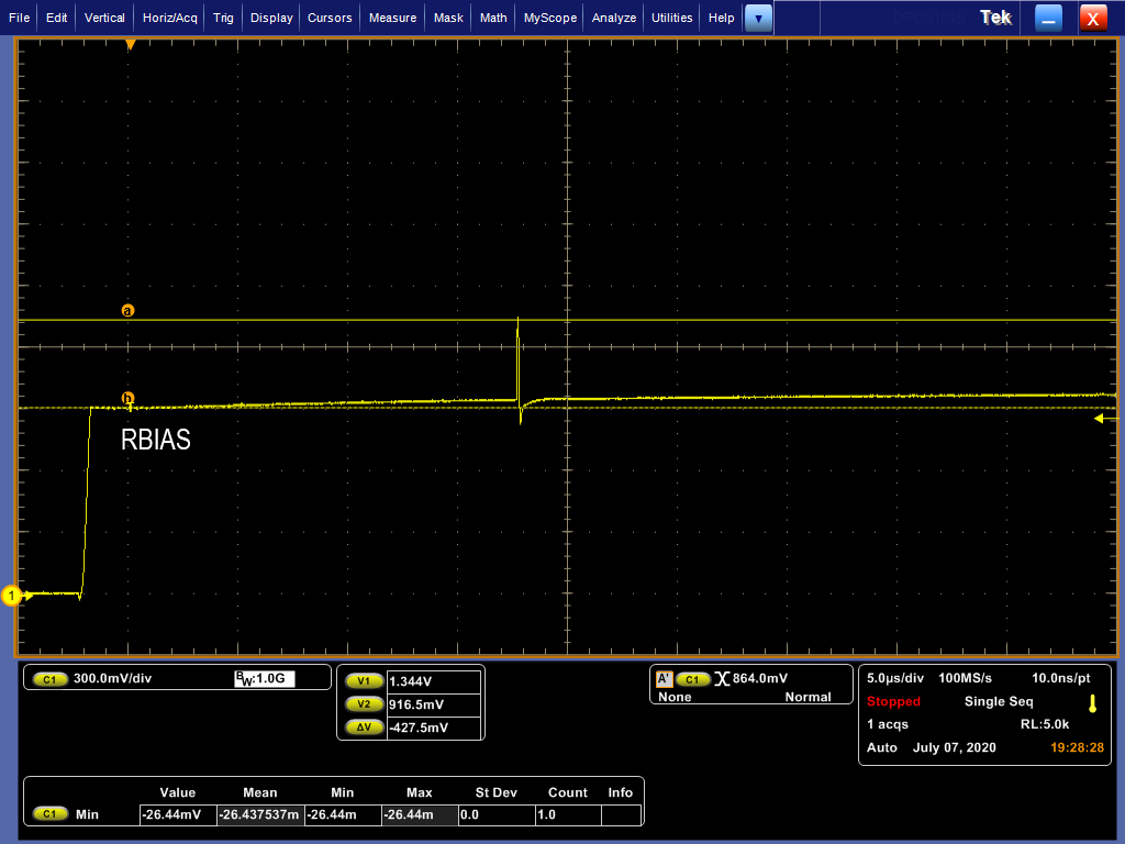
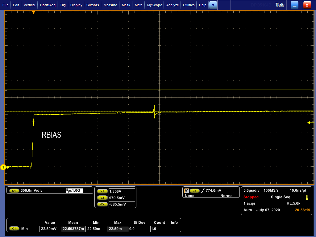
I am using the DP83822H as a PHY transceiver in my circuit, and I've come across some interesting behavior. Whenever the device is slightly warm (around 40 C), the PHY will lose its link. I can consistently recreate this behavior: with an ethernet cable plugged in, blowing some warm air over my PCB causes the link to be lost, and the link is restored whenever the warm air is replaced with cool air. The link is also lost after the board is left on for a while and gets warm, but can be restored by cooling it down. I have seen this behavior on multiple boards, which leads to believe it's a design issue, not a manufacturing issue. Also, I've come across at least two other posts describing similar behavior:

After enabling the "robust" auto-mdix feature and pulling pin 24 low, I am still seeing this issue. Can anyone explain what might be causing this issue? Any other ideas on how to fix this? I'm happy to provide any registers or diagnostic output that might be useful.

Thanks

  • I've done some more investigating and have some more information to report. First, here is the register dump of the PHY when there is an ethernet cable plugged in but it is slightly warm:

    ieee-phy: reg:BMCR(0x00) val:0x3100
    flags: -reset -loopback +aneg-enable -power-down -isolate -aneg-restart -collision-test
    speed: 100-full
    ieee-phy: reg:BMSR(0x01) val:0x7849
    capabilities: -100-b4 +100-f +100-h +10-f +10-h -100-t2-f -100-t2-h
    flags: -ext-status -aneg-complete -remote-fault +aneg-capable -link -jabber +ext-register
    ieee-phy: reg:0x02 val:0x2000
    ieee-phy: reg:0x03 val:0xa240
    ieee-phy: reg:0x04 val:0x05e1
    ieee-phy: reg:0x05 val:0000
    ieee-phy: reg:0x06 val:0x0004
    ieee-phy: reg:0x07 val:0x2001
    ieee-phy: reg:0x08 val:0000
    ieee-phy: reg:0x09 val:0000
    ieee-phy: reg:0x0a val:0x0100
    ieee-phy: reg:0x0b val:0x1000
    ieee-phy: reg:0x0c val:0000
    ieee-phy: reg:0x0d val:0000
    ieee-phy: reg:0x0e val:0000
    ieee-phy: reg:0x0f val:0000
    ieee-phy: reg:0x10 val:0x0002
    ieee-phy: reg:0x11 val:0x0108
    ieee-phy: reg:0x12 val:0000
    ieee-phy: reg:0x13 val:0x0800
    ieee-phy: reg:0x14 val:0000
    ieee-phy: reg:0x15 val:0000
    ieee-phy: reg:0x16 val:0x0100
    ieee-phy: reg:0x17 val:0x00e1
    ieee-phy: reg:0x18 val:0x0400
    ieee-phy: reg:0x19 val:0x8001
    ieee-phy: reg:0x1a val:0000
    ieee-phy: reg:0x1b val:0x007d
    ieee-phy: reg:0x1c val:0x05ee
    ieee-phy: reg:0x1d val:0000
    ieee-phy: reg:0x1e val:0x0102
    ieee-phy: reg:0x1f val:0000
    ieee-phy: reg:0x467 val:0x4f73
    ieee-phy: reg:0x468 val:0000

    Second, I am able to tell when this behavior is occuring without an ethernet cable plugged in, because when the phy is cool and operating properly, it sends a link detect signal out ever couple dozen milliseconds if nothing is plugged in. However, if the device is slightly warm on boot up, no link detect signals ever appear unless a fan blows cold air over the chip.

    , I believe you were helping the other people who encountered similar issues to me. Do you have any ideas what could be causing this? Does this information help?

    Thanks

  • Hi devries,

    You mentioned that the PHY stops sending link detect signal when in normal mode, do you mean the signals on the MDI lines?

    When the PHY is warm, do you have access to the physical pins of the PHY? Can you measure to voltage on the input pins, voltage across RBIAS pin and the output signal clockout pin?

    -Regards

    Aniruddha

  • Hi ,

    Yes, when the PHY is acting normally and no ethernet cable is plugged in, I see a pulse sent out periodically on the TD_P/TD_M and the RD_P/RD_M lines. When the PHY is turned on when warm, it doesn't send out those pulses anymore. 

    And yes, I do have access to the physical pins of the PHY when it's warm, so I can measure the voltage on the pins. Which input pins should I measure? And what pin are you referring to when you say "output signal clockout pin"? Do you mean the XO pin (pin 22)? Lastly, what voltage should I expect to see on the RBIAS pin and other pins?

    Thanks

  • Dear  and ,

    I'm still waiting for instructions on which pin voltages you would like me to measure. In the mean time, I have done some more work on this issue and discovered something else. After the PHY is powered on when warm and does not detect a link (even though a cable is plugged in), I can make the PHY start to work and see a link if I toggle the INT/PWDN pin low, then back to high. So it appears to be an issue occuring when the PHY is initializing. Hopefully this helps narrow down the issue. I hope to hear from one of you soon.

    Thanks

  • Are these posts monitored by TI employees after their initial reply? I asked a clarifying question on Monday and there hasn't been any response. I'm still encountering this issue and l'm still looking for help. Does anyone know if there is another way to get support from TI on their products? Waiting 3+ days before getting any acknowledgement is frustrating.

  • Hi adevries,

    My apologies in getting back to you on this thread. In my previous reply, I meant to ask you if you can measure the voltage on the VDDIO (pin 21) and AVDD (pin 14) to make sure that the voltage are correct. The voltage across RBIAS pin should be around 1V. For clock out, let me take as step back and first confirm if you are using a crystal on XI/XO pin or some other clock source? If you are using another clock source, is the clock source present at the time of power up or does it come up after some time?

    Based on your INT/PWDN experiment, do you see the PHY recover if you apply a reset pulse on the reset pin instead of using the INT/PWDN?

    When the PHY stops sending link pulses, are you still able to read/write registers? Lastly, are you using the recommended land pattern for the PHY as mentioned in page 114 of the datasheet?

    -Regards

    Aniruddha

  • Hi Aniruddha,

    I have measured the voltage on the VDDIO and AVDD pins, and they both look good to me. I measured them at the time the PHY is powered on, and they both power-on at the same time. Please see the oscilloscope capture below.

    The voltage on the RESET_n pin does initially start at a weird voltage during start-up, but it is eventually driven high and toggled once everything is stable, so I think that should be okay. I'm happy to give you more information on that though, if you're suspicious of it.

    For the RBIAS pin I have a 4.87 kohm resistor connected, and nothing else. I captured the voltage on the RBIAS pin when the PHY was first being powered on.

    RBIAS Voltage Normally: 

    RBIAS Voltage During Observed Issue: 

    In both cases, there is an initial voltage spike observed, but it quickly stabilizes to 1V and doesn't change from that value.


    For the clock source, I do not have a crystal connected to the PHY. Instead, I have the PHY in RMII slave mode and provide a 50 MHz clock on the XI pin. The clock source is not initially present when VDDIO and AVDD power on, however, the clock does start a couple seconds after powering my board on, and the RESET_n line is toggled a second or two after that by our software. This toggling is part of the processor's initialization of the PHY and happens both when the PHY starts in a functioning state and when it starts in a non-functioning state.

    I am working on toggling the RESET_n line and hope to report my results on that effort tomorrow.

    When the PHY stops sending link pulses, I can still read/write registers. The list of registers I pasted in a previous post above is from a time when the PHY was encountering the issue I've described.

    I am using the recommended land pattern for the PHY in my design.

    Lastly, I have a picture of my schematic I can share, if you wish to review it. However, I do not want to post it to the forum, so if there is a private way I can send it to you, that would be appreciated.

    For additional information, please see this post where I answered some of Vikram's questions about this issue as well: https://e2e.ti.com/support/interface/f/138/t/920882

    Thanks

  • Hi Adevries,

    Sharing schematic through E2E private chat is possible. I see that you have shared the schematics with Vikram. I will sync with Vikram for suggesting the next steps.

    -Regards

    Aniruddha

  • Hi Aniruddha,

    I wanted to provide a quick update. I was able to toggle the RESET_n line on the phy, and that also appears to fix the issue. While it's tempting to say "the problem is fixed, nothing else needs to be done", I don't like that I can't explain what was causing this issue. Do you have any more ideas on what the issue is? Did you see any problems with the schematic I shared?

    Thanks

  • Hi Adevries,

    The PHY shouldn't change behavior based on temperature. It has been tested across the full temperature range to verify functionality. Recovery after reset points towards some kind of glitch in the PHY operation. From your plots above, it looks like RBIAS has a spike, does it coincide with when the PHY faces the issue? Can you probe the input clock (XI) when the RBIAS spike occurs?

    For the schematic, I will ask Vikram to follow up with you.

    -Regards

    Aniruddha