This thread has been locked.

If you have a related question, please click the "Ask a related question" button in the top right corner. The newly created question will be automatically linked to this question.

DP83822H: Looking for support with a PHY issue

Part Number: DP83822H

Hello,

I posted a different question in this forum at the end of June, and after an initial reply 10 days ago, my responses have been ignored. Is there something else I need to do to get a response? This was the original thread: https://e2e.ti.com/support/interface/f/138/t/917642. I'm still encountering these issues and am still looking for support.

Thanks

  • Hi Adevries,

    I will try my best to support you with debug of this strange but frustrating issue. I will check with my coleagues about the investigation done so far and pitch in from my side. Meanwhile can you please share the following :

    1. Value of pull-down resistor used on pin 24? If possible, do share the schematic for further review.

    2. During the observed issue :

    a. Voltage level of Rbias pin. What all is connected on this pin? What resistor value? Any cap?

            b. Voltage level of int/pwdn_n pin.

            c. Min voltage level of AVD supply

            d. Is rx_clk toggling?

            e. Using IOCNTRL1/2 registers can you bring out XI clock (25MHz) and free running clock (125MHz) on accessible pins and check their frequency? Also does cooling down and warming up, change these frequencies or introduce glitches (may be you can plot the eye diagram of these while warming up )

    3. Are you using crystal or clock source? When you are blowing air, do you think that crystal will also be getting heated up?

    These will help in accessing the health of phy by looking at some internal voltages and clock.

    --

    Regards,

    Vikram

  • Hi Vikram,

    Thank you for the reply. I have pin 24 pulled low using a 2.43 kOhm resistor. I have a schematic I can send you, but I would prefer to not post it on the forum. Is there an email address I can send it to instead?

    I am working on getting answers to your other questions. I can tell you that I have a 4.87 kOhm resistor connected to the RBIAS pin, with no capacitor connected. Also, I am not using a crystal on this design. Instead, I have a 50 MHz clock signal I am providing directly to pin XI.

    Thanks

  • Hi,

    I have sent you request to connect over e2e. It will have my email id.

  • Hi Vikram,

    I was able to measure basically all of the signals you requested using an oscilloscope. I have captures from when the PHY is acting normally and when the issue is occuring. Please find the signal captures below.

    **********************************

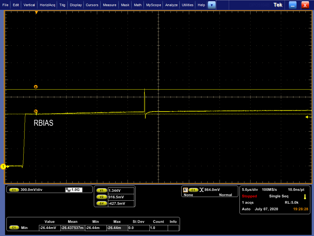
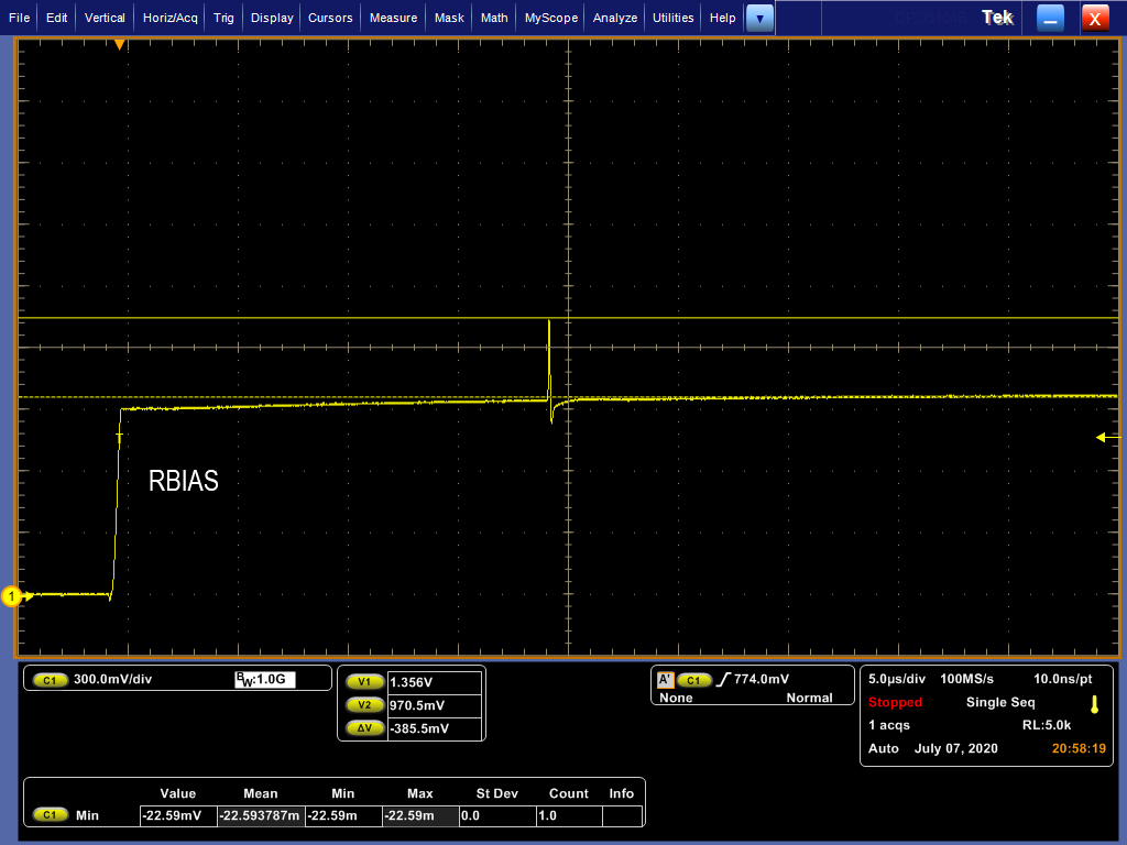
    RBIAS pin: On this pin I have a 4.87 kohm resistor connected, and nothing else. I captured the voltage on the RBIAS pin when the PHY was first being powered on.

    RBIAS Voltage Normally: 

    RBIAS Voltage During Observed Issue: 

    In both cases, there is an initial voltage spike observed, but it quickly stabilizes to 1V and doesn't change from that value.

    **********************************

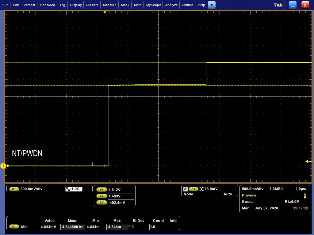
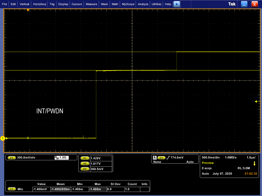
    INT/PWDN_n Pin: On this pin I have a 10 kohm resistor pulling the signal high and a GPIO pin from the board's processor driving this pin (once the processor powers on and is initialized). I captured the voltage on this pin when the PHY was first being powered on.

    INT/PWDN_n Voltage Normally: 

    INT/PWDN_n Voltage During Observed Issue: 

    In both cases, the voltage sits at 1.4V for a couple seconds before going all the way to 1.8V, but again, I don't see any significant difference between these two measurements.

    **********************************

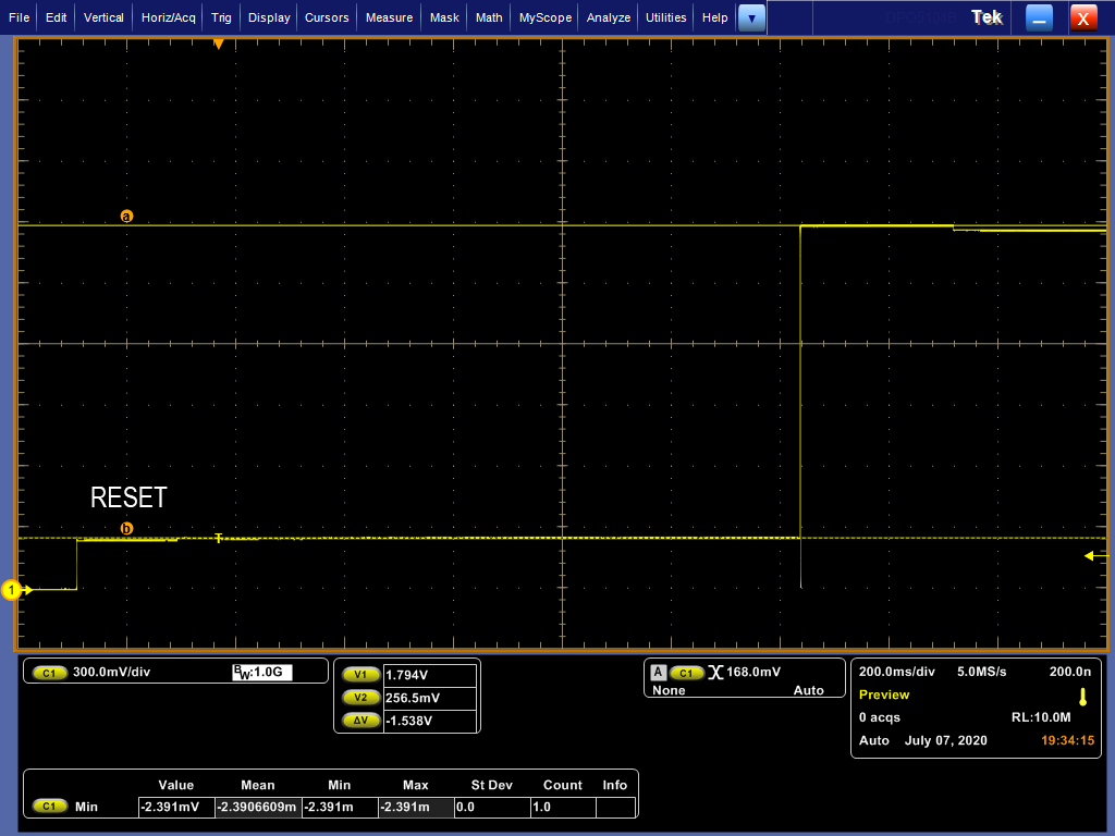
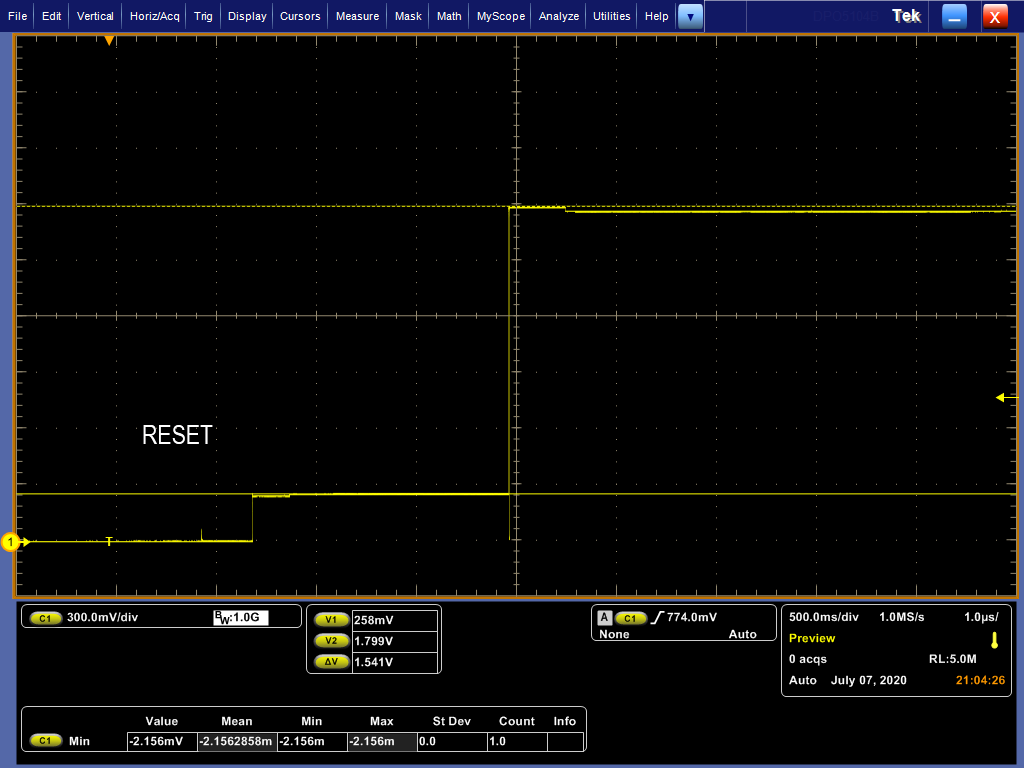
    RESET_n Pin: On this pin I have a 1.96 kohm resistor pulling the signal low and a GPIO pin from the board's processor driving this pin (once the processor powers on and is initialized). I captured the voltage on this pin when the PHY was first being powered on.

    RESET_n Voltage Normally: 

    RESET_n Voltage During Observed Issue: 

    In both cases, the voltage sits at 0.25V for a couple seconds before going all the way to 1.8V, but again, I don't see any significant difference between these two measurements. Additionally, a few seconds after this occurs, the processor pulls the reset line low for 2ms, and that also looks identical in both situations.

    **********************************

    AVD Minimum voltage: On this pin I measured the steady state voltage for a couple minutes and recorded the minimum voltage measured by the oscilloscope during that time.

    AVD Minimum Voltage Normally: 1.803V

    AVD Minimum Voltage During Observed Issue: 1.796V

    There appears to be a very slight voltage drop, but that doesn't appear to be significant, and it's within the recommended AVD voltage limits.

    **********************************

    RX_CLK Pin: I have this pin disconnected and do not see any clock signal on this pin in either situation. I do not expect to see a clock signal on this pin because I am operating the PHY in RMII Slave Mode.

    **********************************

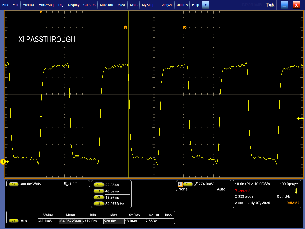
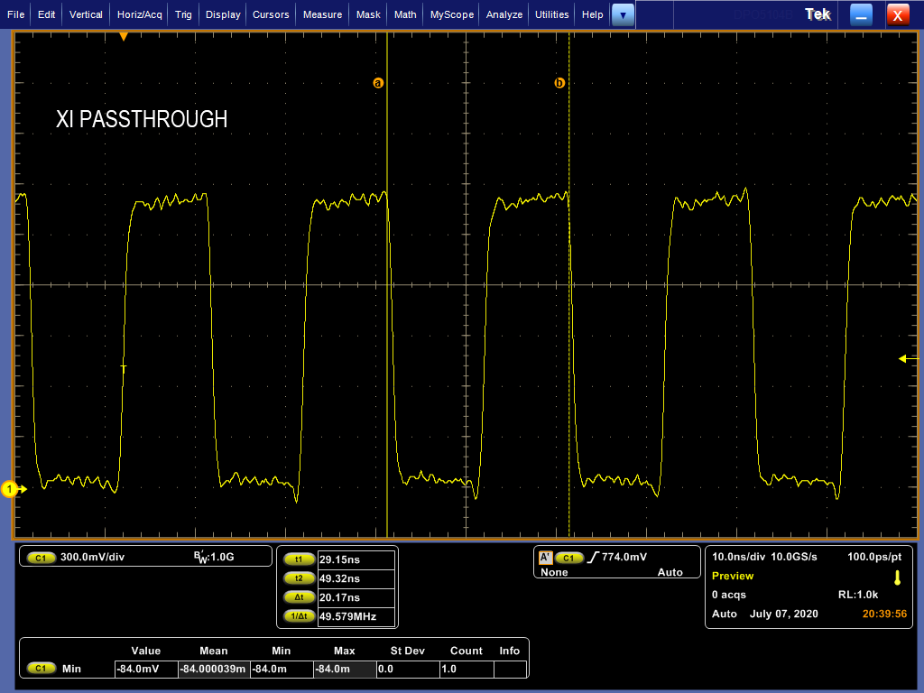
    XI Clock: I brought out the XI clock to GPIO1 and measured it on that pin. Because it does not come out of that pin by default, I was unable to capture the voltage when the PHY was first being powered on, and instead captured the steady-state behavior of the clock in both situations.

    XI Clock Voltage Normally: 

    XI Clock Voltage During Observed Issue: 

    The clock signal looks the same to me in both situations.

    **********************************

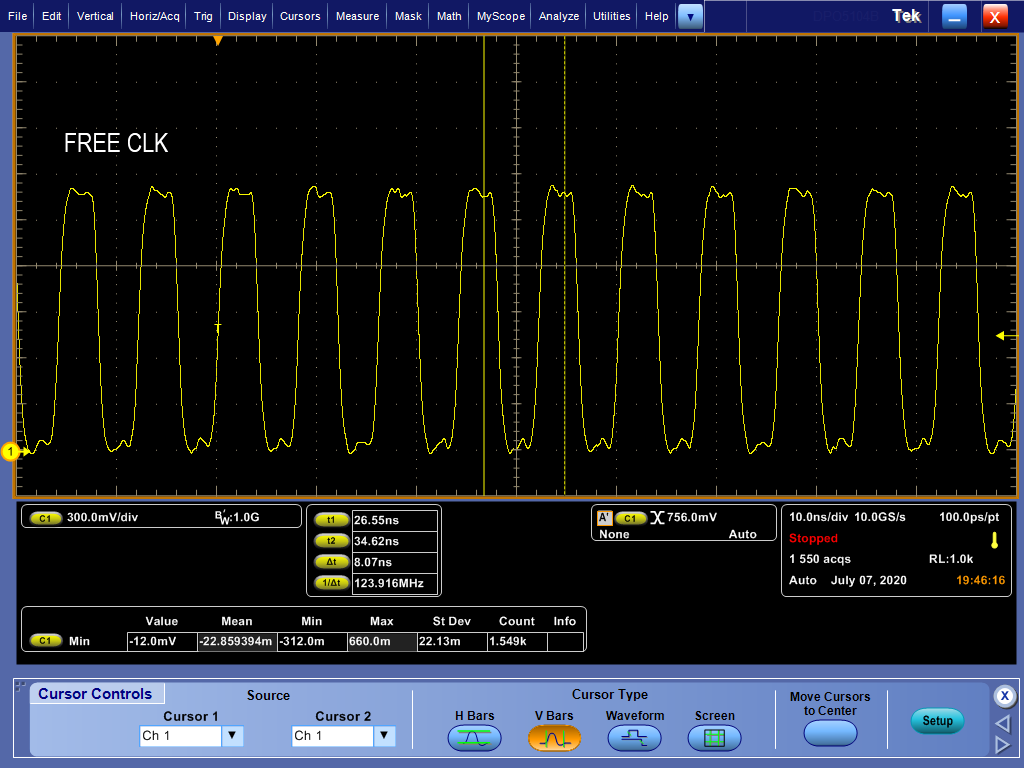
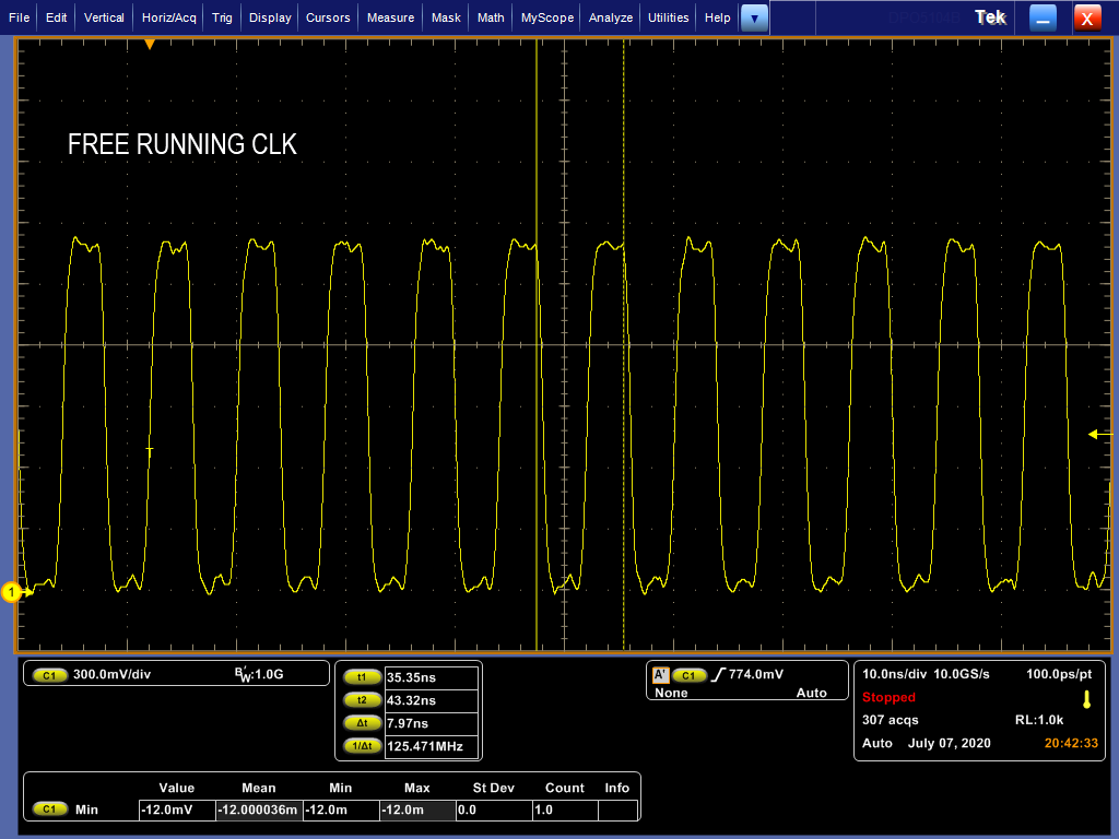
    Free Running Clock: I brought out the free running clock to GPIO1 and measured it on that pin. Because it does not come out of that pin by default, I was unable to capture the voltage when the PHY was first being powered on, and instead captured the steady-state behavior of the clock in both situations.

    Free Running Clock Voltage Normally: 

    Free Running Clock Voltage During Observed Issue: 

    The clock signal looks to same to me in both situations.

    **********************************

    I will see if I can get an eye diagram of clock signals. In the meantime, please let me know if this helps and if I can capture any other data that might be useful in diagnosing this issue.

    Thanks

  • Hi,

    Thanks for sharing the data. This data looks clean.Lets see if we can catch some glitches or bad pulses in eye diagram of 25MHZ clock.

    And you mentioned earlier that :

    1. Normal case : You see pulse on the copper line- connector (without cable)

    2. Heated-up case : Line is silent.

    Is that correct?

    Also have you already shared schematic? Is pin 24 also connected to any other module on the board (other than pull-down resistor?)

    --

    Regards,

    Vikram

  • Hi Vikram,

    That is correct. I only see the keep-alive pulses in the normal case. Pin 24 is only connected to a pull-down resistor. And yes, I believe I sent you the schematic via a private message. If you didn't get it, or want me to send it to you another way, I'm happy to do that. I didn't see an email address I could send it to originally, so if you would prefer that, just PM the email address I should send it to.

    Thanks

  • Hi,

    Yes I received your schematic. Thankyou.

    Were you able to "sweep" the temperature and get the eye diagram of clocks on the fly? It will help us verify that there are no glitches in the clock (pll unlocking, oscillator misbehaving etc) when you heat up the device.

  • Hi Vikram,

    I attempted to get an eye diagram today, but my oscilloscope does not have the capability, sorry. If there is another measurement I can take that would help instead, I'm happy to do that. 

    Thanks