This thread has been locked.

If you have a related question, please click the "Ask a related question" button in the top right corner. The newly created question will be automatically linked to this question.

DP83TD510E-EVM: Could not establish communication between two boards (Mode: Auto Negotiation)

Part Number: DP83TD510E-EVM
Other Parts Discussed in Thread: USB-2-MDIO, DP83822I, DP83TD510E

Hi Support Team,

I try to connect two evaluation boards DP83TD510E-EVM together and establish a link between two communication partners, e.g. 2 Raspberry Pis. 

I would like to evaluate the "Auto Negotiate" feature. 

After I read the users manual and all previous threads I try to run Both boards with the same setup:

J12: Vin: 24 VDC

J14, J15, J16 -> Internal power

USB 5 V -> removed

J17, J18: 1

J20: 0

J19, J26, J27: As delivered (LED_0, EXT, EXT)

The behavior:

When I power on the board, (communication partners are already powered on) the LED D15 is on for 2-3 seconds. Then it turns of on both boards, the link is established from each communication partner, but they cannot reach each other.

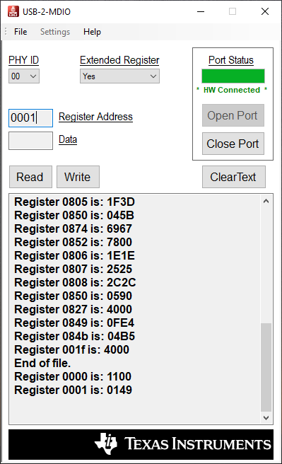
Then I connect the USB-2-MDIO Tool and load the Script "AutoNegotiation_Initialization.txt" to both boards (PHY ID 0)

After that, one LED D15 stays on (see picture attached). So the 1.st partner cannot establish the link to DP83822.

Question:

1. Can I use both boards with AutoNegotiation_Initialization.txt or do I have to use Master-Slave mode?

2. If Master-Slave: Do I need to change the hardware?

3. Do I need to configure the DP83822I (PHY ID 5)?

4. Which configuration is loaded to the DP83TD510E after power-on-reset?

5. Do you see any mistakes in my sequence?

I attached some pictures from my setup to this post. 

Thanks in advance and best regards,

Tommy

  • Hi Tommy,

    The steps you have followed appear correct. Can you verify that you are able to read/write registers with the USB-2-MDIO tool? Reading register 0x0000 or 0x0001 as an example?

    1. Can I use both boards with AutoNegotiation_Initialization.txt or do I have to use Master-Slave mode? 

    Using the Auto-Negotiation initialization script on both EVMs is enough to establish link between two DP83TD510E devices.

    2. If Master-Slave: Do I need to change the hardware?

    No, the Forced Master or Forced Slave modes do not require any hardware changes.

    3. Do I need to configure the DP83822I (PHY ID 5)?

    No, the DP83822I is strapped to support the 10Mbps media converter mode in over the RMII interface.

    4. Which configuration is loaded to the DP83TD510E after power-on-reset?

    The DP83TD510E will be strapped into RMII Master mode with LED_0 = 0 setting. The auto-negotiation initialization is needed on this sample to configure link. 

    Regards,
    Justin 

  • Hi Justin,

    thanks for the fast response!

    I configured both boards again with the script AutoNegotiation_Initialization.txt.

    I can read out both registers (0000 is always 1100, 0001 is 0149 after writing the script, and 016D after re-connecting the USB):

    These values are the same for both boards.

    My issue remains, connecting board 1 to the communication partner, everything seems to be OK (D15 off - link established):

    For board 0 the LED D15 stays always on, and the com partner couldn't establish a link to the DP83822:

    So is the conclusion that the hardware from board 0 might be faulty?

    Regards,

    Tommy

  • Hi Tommy,

    Can you try toggling the PHY Reset S4 switch on board 0? Does a reset of the DP83822I result in link established over the RJ45?

    Regards,
    Justin 

  • Hi Justin,

    strange behaviour, but when I execute the steps as followed I am able to establish a connection between my communication partners:

    1. Power down, Communication partners connected to DP83822

    2. Power up both boards at the same time.

    3. Connect Board 0 to USB and parametrize with script "AutoNegotiation_Initialization.txt" - disconnect USB

    4. Connect Board 1 to USB and parametrize with script "AutoNegotiation_Initialization.txt" - disconnect USB

    5. Push Button S4 (PHY RST) only on board 0!

    -> Communication is established successfully. These steps are reproducible.

    Can you maybe provide a firmware (.hex file) for the MSP430 that initialize the PHY00 with AutoNegotiation_Initialization at startup?

    Thanks for your support!

    Best regards,

    Tommy