This thread has been locked.

If you have a related question, please click the "Ask a related question" button in the top right corner. The newly created question will be automatically linked to this question.

DS90UB954-Q1EVM: DS90UB954-Q1EVM

Part Number: DS90UB954-Q1EVM
Other Parts Discussed in Thread: ALP

Hello TI,

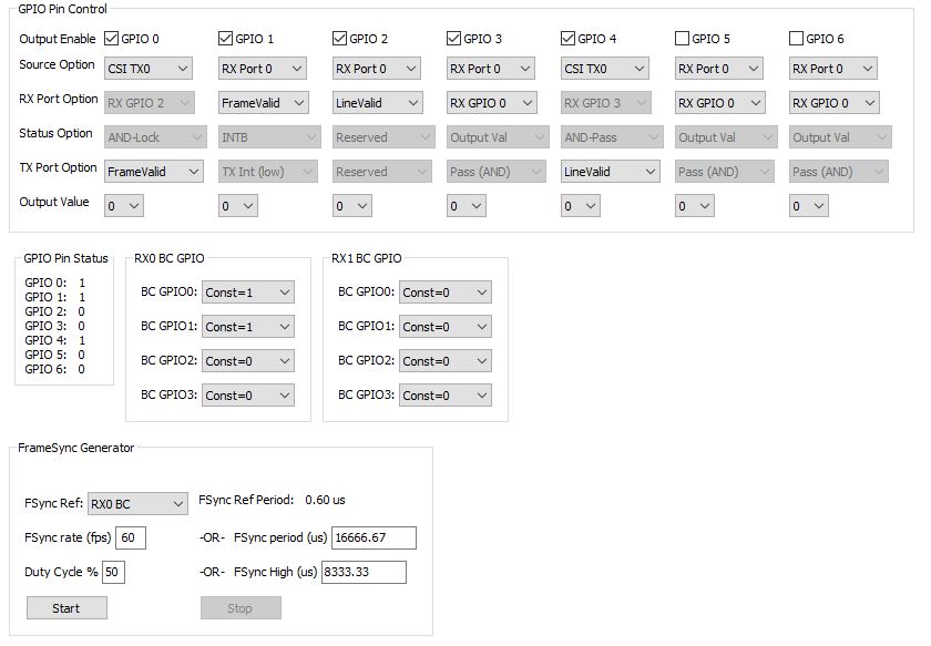
I am struggling to display the MIPI CSI-2 image from the 954-Q1EVM / 953-EVM kits. After probing, I do not see the reference clock 25 MHz active from your 954-Q1EVM. How do I make the Ref CLK active? I am sending the POC voltages and the Pass and Lock LED's are lit on the 954-Q1EVM. 

I am using a Cypress CX3 Denebola RDK eval board with a custom adapter board to link the differential CSI data lines, CLK lines, and I2C lines between the CX3 and your 954-Q1EVM. 

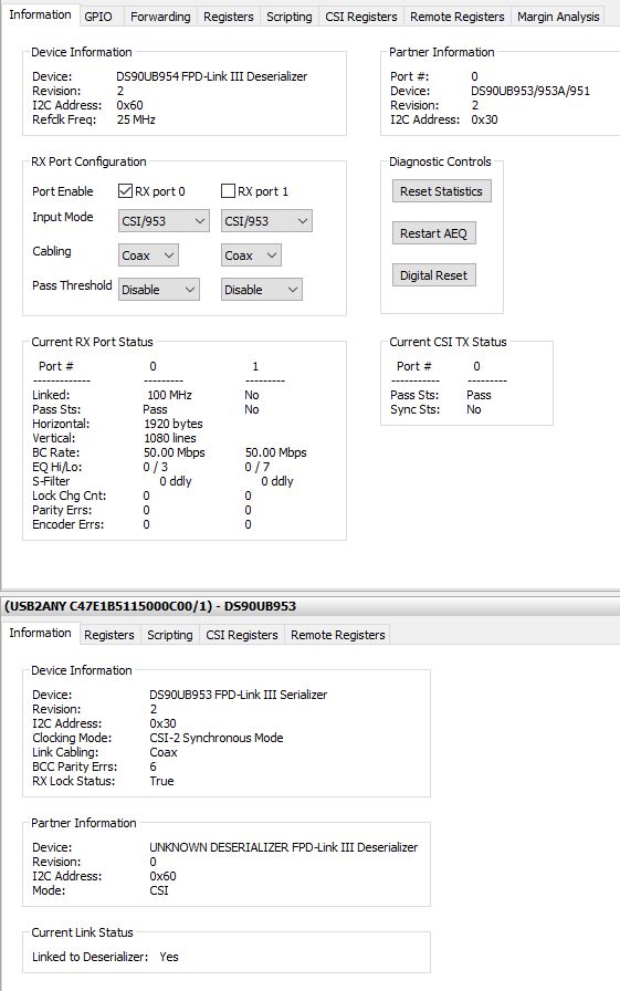
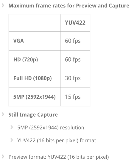
Below is my status after running the following Python scripts ( 954_script_A1_RX0_init_CSI0_broadcast.py    and    ovt_1280_1080_30fps_REMOTE_RevE2_ID7a.py). Please help provide any additional Python code I need to run to ensure the link is proper. Can you send me the Python Scripts to my email?  emilio.cuesta@te.com

My concerns are listed below:

-REF CLK not seen from the J24 connector 

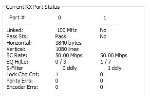
- "Current CSI TX Status" Port 0 Sync Status shows "No" , but the Pass Status displays "Pass". Maybe the REF CLK not being seen can be a cause.  

Thank you for your assistance!


  • Hello Emilio,

    Based on the screen shots it appears everything is working fine. As a debug step, you could map the frame valid and line valid signals from RX0 or CSI0 out to GPIOs on the 954 EVM in the GPIO tab, then probe them to see if they are toggling at the expected rates.

    Also, are you using the top side or bottom side connection for the CSI-2 connection? If you are using the bottom side connection, you need to populate 0 ohm resistors to connect to the other side and remove the top side 0 ohms (see the EVM user's guide for details).

    Best Regards,
    Casey
  • Hello Casey!

    Thank you for your timely response! I am using the top CSI-2 connection so there is no need to manipulate placed resistors right? Could you help provide verify my GPIO mapping is correct as you described? My attempt shown below... The GPIO LED's lit, results seen below (screenshot attached). What frequency should the CSI reference clock be? This is not seen and the Sync Status is set to "No" in my first screenshot. 

    GPIO 1 = 30 Hz with high duty cycle

    GPIO 2 = 34 KHz 

    GPIO 4 = 34 KHz

  • Hello Emilio,

    Top side - no need to manipulate resistors.

    The indicator measurements also show things are working correctly. The GPIO1 is showing the frame rate. The GPIO2 and GPIO4 are showing the line rate. Both look correct based on your setup.

    The CSI clock is a different clock then "REFCLK". The CSI clock speed depends on what CSI data rate you have programmed for the output. You can see it in the forwarding tab of the GUI.

    Best Regards,
    Casey
  • Hello Casey,

    Thank you... I now understand the CLK differences. I verified my CSI CLK lines are feeding correctly to the Cypress CX3. The clock must be too fast for the O-scope I have on hand (100MHz)...

    I currently have the Sync Status Set to "No" (see attached). Does this sync need established? If so, how? Thank you!

    BR,

    Emilio

  • Hello Emilio,

    Sync status is only applicable for synchronized forwarding modes which can be enabled when you have multiple imager inputs. In this case it can be ignored.

    Best Regards,
    Casey
  • Hello Casey,

    Thank you! Still is not working... Could you help send me the "P542_A0_RX0_CSI_Enable.py" and the "ovt_1920_1080_Remote.py" scripts? I do not see these exact scripts in the Program Files.... These scripts are referred to on page 6 of the 953-Q1EVM users guide. I am not sure if the scripts I am using is not providing exactly what I need for the CX3 Cypress chip... I am using the CX3 Cypress eval board from my past support thread Vishay recommended... e2e.ti.com/.../773499

    Thank you!
  • Hey Emilio,

    We need to update the 953EVM user's guide since those scripts are outdated. The first one was for prototype silicon and the second is very similar to the 1280x720 you already have. Again, the 954 appears to be correctly outputting data.

    Do you know what exact format you are expecting to receive?
  • Hello Casey,

    I am expecting an MIPI CSI-2 video link... If there are other formats contained in the CSI-2 standard, I was not aware... As mentioned I am using the CX3 Cypress Chip which TI recommended me to use in my previous forum with Vishay https://e2e.ti.com/support/interface/f/138/t/773499 , so hopefully it is a simple format re-configuration. Attached is what I found in the CX3 documentation stating YUV422 format (16 bits per pixel). Is this configurable on your 953/954 Eval boards?    

  • Hello Emilio,

    First of all, the OV10640 image sensor outputs only RAW data formats. Second, the CX3 definately supports other CSI-2 formats including RAW and RGB. Third, 954 can support all the standard CSI-2 formats but it has no ability to convert incoming data to a different format on the output. It will simply pass the format through in the CSI-2 headers. 

    Please consult Cypress on proper configuration of the CX3 as we can not provide support in this area. 

    Best Regards,

    Casey 

  • Hello Casey,

    Thank you!

    So, is the RAW data format coming from the 954-Q1EVM CSI-2 connector J24? Do I need to move my jumper on J15 where you can select CSI, RAW12L, RAW12H, or RAW10. I am currently using the CSI mode at the J15 header. What format is leaving the 954-Q1EVM when using the 953-Q1EVM? Do you have python code available to send 1920x1080p 30fps from the OV10640? 

    Thanks again!

    Emilio

  • Emilio,

    CSI-2 is the data transfer protocol. The CSI-2 protocol can carry various different data types within it including RGB, RAW, YUV, etc.

    The 953 and 954 can support all these formats, they just pass them through with whatever format carrier is contained within the data.

    In the setup which you have been using with the OV10640 example, the format is RAW because that it what the OV10640 outputs. We don't have a script for 1920x1080, but we have both RAW12 and RGB888 pattern generator scripts for 1080p30 if you would like to test those. They are in this folder of the ALP install:

    C:\Program Files (x86)\Texas Instruments\Analog LaunchPAD v1.57.0010\PreDefScripts\DS90UB954

    Best Regards,
    Casey
  • Hello Casey,

    I want to make sure I am running all the correct scripts. Previously, I ran 954_script_A1_RX0_init_CSI0_broadcast.py THEN ovt_1280_1080_30fps_REMOTE_RevE2_ID7a.py and in that order... Does it matter the order? For your proposed test, do I solely run the RAW12 1080p script as a test and do I solely run the 1080p RGB888 pattern generator as a test? Are there other scripts I must run prior to or after the 1080p scripts? Thank you!

    Emilio
  • No, you do not need to run anything prior to the pattern generator scripts.

    Best Regards,
    Casey
  • Hello Casey,

    I tried your recommendation, but still no success. I reached out to the Denebola CX3 support engineer and he mentioned the image format is YUY2. Is this image format achievable on your TI boards? Thank you!

    Emilio

  • Hey Emilio,

    I don't have a premade script to provide for doing a patgen in that format, but yes we can support that CSI format (it is a subtype of YUV422).

    But again, I am certain that the CX3 can support more formats than this. Please work with Cypress on debugging this issue.

    Best Regards,
    Casey
  • Hello Casey,

    I am emailing the Cypress CX3 engineer. The CX3 supports RAW CSI format; however, firmware needs written for my CX3 evaluation board to receive and process the RAW format. Could you (TI) help provide support to develop the YUY2 patgen python script? What is required to develop this script and can TI support? Thank you!

    Best Regards,

    Emilio  

  • Hello Emilio,

    Here is a script we were able to dig up which does a PATGEN from 953 and sends it to 954 (so you need to have them connected). Just double check that your device addresses match.

    import time

    # 953 config

    Alias953 = 0x18
    DES954 = 0x60


    # Reset 954
    board.WriteI2C(DES954, 0x01, 0x01)
    time.sleep(1.0)
    # CSI enable , continuous clock, 4 lanes
    board.WriteI2C(DES954, 0x33, 0x03)
    time.sleep(0.1)
    # Set CSI_TX_SPEED to select 800Mbps
    board.WriteI2C(DES954, 0x1F, 0x02)
    time.sleep(0.1)
    # Port Control
    board.WriteI2C(DES954, 0x0C, 0x83)
    time.sleep(0.1)
    # Port Selection
    board.WriteI2C(DES954, 0x4C, 0x01)
    time.sleep(0.1)
    # set alias
    board.WriteI2C(DES954, 0x5C, 0x18)
    time.sleep(0.1)
    board.WriteI2C(DES954, 0x20,0x00) # forwarding of all RX to CSI0
    time.sleep(0.1)
    if (board.ReadI2C(Alias953, 0x00, 0x01) != 0x30):
    print "953 ID Error"
    else:
    print "953 ID Ok"

    # Reset 953
    board.WriteI2C(Alias953, 0x01, 0x01)
    time.sleep(1.0)
    # enable pat gen
    board.WriteI2C(Alias953, 0xB0, 0x00)
    board.WriteI2C(Alias953, 0xB1, 0x01)
    board.WriteI2C(Alias953, 0xB2, 0x01) #enable pattern generator

    board.WriteI2C(Alias953, 0xB1, 0x02)
    board.WriteI2C(Alias953, 0xB2, 0x33) #fixed color pattern, 8 color bars, block size of 5

    board.WriteI2C(Alias953, 0xB1, 0x03)
    board.WriteI2C(Alias953, 0xB2, 0x1E) #CSI Data Identifier (0x24 = RGB888, 0x2C = RAW12, 0x2B = RAW10)

    board.WriteI2C(Alias953, 0xB1, 0x04)
    board.WriteI2C(Alias953, 0xB2, 0x0f) #line size (15:8)

    board.WriteI2C(Alias953, 0xB1, 0x05)
    board.WriteI2C(Alias953, 0xB2, 0x00) #line size (7:0)

    board.WriteI2C(Alias953, 0xB1, 0x06)
    board.WriteI2C(Alias953, 0xB2, 0x01) #bar size (15:8)

    board.WriteI2C(Alias953, 0xB1, 0x07)
    board.WriteI2C(Alias953, 0xB2, 0xe0) #bar size (7:0)

    board.WriteI2C(Alias953, 0xB1, 0x08)
    board.WriteI2C(Alias953, 0xB2, 0x04) #active lines per frame (15:8)

    board.WriteI2C(Alias953, 0xB1, 0x09)
    board.WriteI2C(Alias953, 0xB2, 0x38) #active lines per frame (7:0)

    board.WriteI2C(Alias953, 0xB1, 0x0a)
    board.WriteI2C(Alias953, 0xB2, 0x04) #total lines per frame (15:8)

    board.WriteI2C(Alias953, 0xB1, 0x0b)
    board.WriteI2C(Alias953, 0xB2, 0x65) #total lines per frame (7:0)

    board.WriteI2C(Alias953, 0xB1, 0x0c)
    board.WriteI2C(Alias953, 0xB2, 0x0b) #line period (15:8)

    board.WriteI2C(Alias953, 0xB1, 0x0d)
    board.WriteI2C(Alias953, 0xB2, 0x93) #line period (7:0)

    board.WriteI2C(Alias953, 0xB1, 0x0e)
    board.WriteI2C(Alias953, 0xB2, 0x21) #vertical back porch

    board.WriteI2C(Alias953, 0xB1, 0x0f)
    board.WriteI2C(Alias953, 0xB2, 0x0a) #vertical front porch

    board.WriteI2C(Alias953, 0xB1, 0x10)
    board.WriteI2C(Alias953, 0xB2, 0x00) #1st byte of fixed color

    board.WriteI2C(Alias953, 0xB1, 0x11)
    board.WriteI2C(Alias953, 0xB2, 0x00) #2nd byte of fixed color

    board.WriteI2C(Alias953, 0xB1, 0x12)
    board.WriteI2C(Alias953, 0xB2, 0xFF) #3rd byte of fixed color

  • Hello Casey, 

    I modified the 3rd line to show the correct I2C address (0x30). I also needed to indent the print commands inside the if/else in the middle of the code. Lastly, I changed the first line of "# set alias" to correct the I2C address for the 953. I ran the code successfully, but no image displayed through the CX3 board.

    Is this code meant for the YUY2 format? Thank you!

    Best Regards,

    Emilio

  • Hello Emilio,

    Yes, the code should match your format expectations. If it still does not I work I believe this to be a configuration issue of the CX3. We can not support any more detailed configuration of this system beyond our device, so if you need further support we can direct you towards a third party as another resource.

    Best Regards,

    Casey

  • Hello Casey,

    Thank you so much for your assistance as we worked through debugging! Have a good one!

    Best Regards,

    Emilio

  • Hello Casey,

    Could you help provide a Python script to output a YUY2 formatted image using 2 CSI-2 data lanes? I believe what you provided earlier is for a 4 lane output. What needs changed to make the Python script output the data using 2 CSI-2 lanes? Thank you!

    Best Regards,

    Emilio 

  • Emilio,

    The CSI-2 transmitter is enabled with register 0x33. In the provided scripts, simply change bits [5:4] to [1,0] for 2 lanes, so set register 0x33 = 0x23 instead of 0x03.

    Best Regards,
    Casey
  • Hello Casey,

    Perfect. This change is implemented and verified. Can I change the frame rate from the Image sensor provided in the 953 kit? I believe it is currently set to 60Hz. Can I change it to 30Hz with a 1920 x 1080 resolution? Thank you!

    Emilio 

  • Hello Emilio,

    Unfortunately we are not experts on the image sensor configuration since it is not made by TI. We have one configuration to provide to customers, but for any further configuration I would ask that you please contact the image sensor vendor. Our primary focus is to support our FPD Link SERDES devices.

    Best Regards,
    Casey
  • Hello Casey,

    TI provides 1920x1080 at 30Hz found in the PreDefScripts; however, those scripts are raw format. The script you provided to me (YUY2 format) provides a different resolution, see attached. Can the script you provided be modified for a 1920x1080 at 30 Hz? What lines in the code need changed? Thank you!

    Best Regards,

    Emilio

  • Emilio,

    The script provided is YUV2 (YUV422 8 bit format). For 8 bit YUV, there are 2 bytes per pixel, so the horizontal line size is double the horizontal active pixels. The resolution is correct.

    Best Regards,
    Casey
  • Hello Casey,

    Yes, I agree with the resolution. Thank you! How can the frame rate be controlled through the script you provided? I would like to make sure the frame rate is 30 Hz. Thanks again!

    Best Regards,
    Emilio
  • Emilio,

    The line period, line length, and total lines per frame control the frame rate. Line period can be adjusted in register 0x0C and 0x0D

    Best Regards,
    Casey
  • Hello Casey,

    How is this implemented? Through code or through the GUI? The attached shows the registers you referred to through the GUI. How would l create a 30 Hz frame rate? Line period should be 0.033333 seconds... How do I implement? Thank you!

  • Emilio,

    The 0x0C and 0x0D registers I was referring to are in the PATGEN indirect registers. Please referce datasheet section 7.5.11 for information on accessing the PATGEN registers and configuring PATGEN. It can be done through the GUI either in the register tab or by editing the script I provided. The line period in DEC is calculated with the following equation:

    ROUND(1/("Frame Rate in Hz"*"Total Lines*0.00000001),0)

    I can confirm that based on the script I gave you it should already be at 30Hz because total lines were 1125, line period is 2963*10ns

    Best Regards,
    Casey
  • Thank you Casey! 

    After some probing I verified the CSI Data Lanes 0 and 1 are active as they should be, but the clock from Pins 5 and 7 are not active. I do not have a clock from your board. How can we further troubleshoot? Thank you!

    Best Regards,

    Emilio 

  • Disregard... I think I found the clock... Should the clock be a 1.3KHz 30mV peak to peak signal? 

  • Emilio,

    The peak to peak seems low but I don't know how you are measuring it.

    This thread is really going on quite long and I think maybe for this project you may require more support than we can provide in this forum. Maybe one way to get you the assistance that you need would be to link you up with one of our third party partners who develop systems using our devices. You could potentially interface with them to get you up and running quicker?

    Best Regards,
    Casey
  • Hello Casey,

    I am using a 100MHz oscilloscope and probing on the differential clock out pins from the 954 board. Who would you recommend for further support? I only knew this option for support. Thank you!

    Best Regards,

    Emilio Cuesta

  • Hello Emilio,

    The 100MHz scope is too low to measure the CSI CLK. By default the clock should be 400MHz if you haven't changed the CSI transmitter speed. 

    We have third party partners who build system solutions with our devices which may be able to assist you in accelerating your project development. I would recommend reaching out to D3 Engineering or Leopard Imaging. 

    Best Regards,

    Casey