This thread has been locked.

If you have a related question, please click the "Ask a related question" button in the top right corner. The newly created question will be automatically linked to this question.

TPS65982: TPS65982ABZBHR

Part Number: TPS65982
Other Parts Discussed in Thread: TPS54531

Hi : 

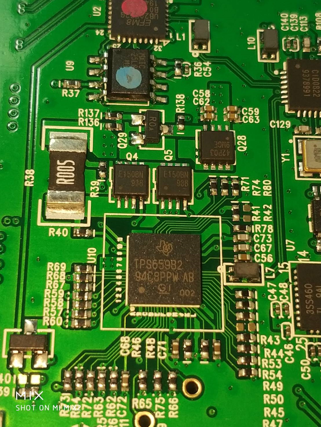
         The TI TPS65982ABZBHR  is new chip 

         We test the PD DOCK ,  the dock have  5 PDO  5V/ 9V/ 12V/ 15V /20V

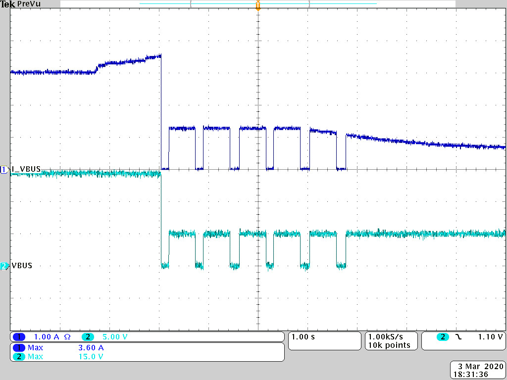
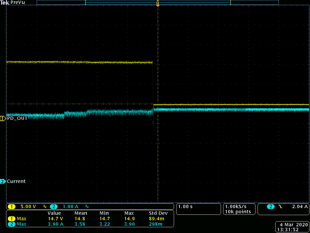
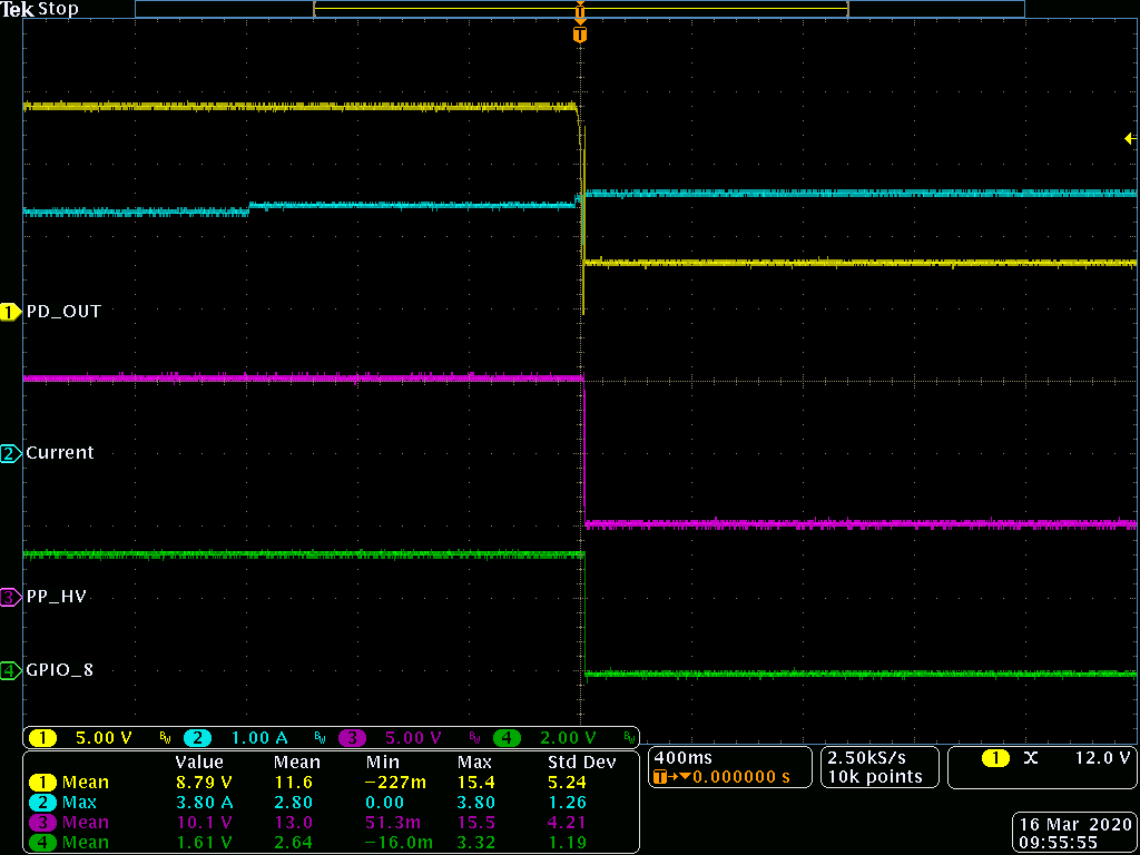
         When test the over current , the PDO 15V  not have over current protect , so the chip burn . 

         But when user the same PD Docking  chip is TPS65982ABZQZR  the PDO 15 have over current protect. 

          Note ; user the same FW version , the same DOCK  only chip different . 

           Please help analysis the problem, Thanks!


  • Hi Sir,

     Please check the attached file for Ted's test bin and pjt.

    1. Use the same PCB/Bin. 9V/12V/15V is through PPHV.

    2. Using ZQZ package device is ok.

    3. Using ZBH package device is turned out when the e-load is set to more than 4A (no OCP triggered for 15V3A 100% setting). 3 devices are burned at the test.

    Can you test it at your side and confirm the issue? Thanks.

    Best regards,

    Gary Teng

    test.zip

  • Hi Gary,

    Which version of the GUI tool are you using? Also, what is the firmware base image that you are using?

    Do you have any scope captures of the failure?

  • Hi Gary , Adam :

                                 The first use old GUI 3.10  , the FW base image is  1.12.06 check the ZBH package chip function .

                                 And there is a synchronous retest GUI _5.13 , the FW base Image 1.12.09 Image, the issue is the same.


  • Hello Ted,

    The only difference between TPS65982ABZBHR and the TPS65982ABZQZR is the package which should not have an effect on the performance of the OCP functionality.

    I recommend downloading the latest configuration tool following the link below. You will then open a new project, and then import the settings from your existing from by clicking Project -> Import Settings from Project.

    Also can you share with me your new project file, a scope capture of the failure, and a detailed description of your test leading up to the failure?

    http://www.ti.com/tool/TPS6598X-CONFIG

  • Hi Adam: 

                    The attached is test GUI 5.13 , FW base Image 1.12.09 . 

    The DOCK setup 5 PDO 5V 9V/ 12V/ 15V/ 20V

    PP5V----PDO 5V OCP 100% ; PPHV ---PDO 9 /12/15V OCP100 % ; EXT_PW ---PDO 20V OCP 100%
    we test PDO 9V/ 12V Over current ----yes at 3.6A protect, but but when PDO 15V load 3.6A not have current protect , can last load cuurent over up the 4A. But at this time the PDO power supply is wrong and the IC is damaged

    TI_TPS65982 GUI 5_13_FW1_12_09.zip

  • Hi Adam:

                            We try the new GUI tool , the FW Base image  1.12.09 

                            Test the PDO 15V Over current  no protection . 

                             We want to emphasize that the same FW and PCBA When using New chip TPS65982ABZBHR, it is impossible to protect against over current 

                              at PDO 15V,while earlier chip TPS65982ABZQZ can.

                              Can you please test it on the TI EVB Board, I believe it is easy to cop


  • Hi Ted,

    I am covering this issue while Adam is out on business travel. We do not have a TPS65982 with the ABZBHR package on hand, but I ordered some this morning and will be able to test this issue in a few days when they arrive.

    In the meantime, could you please send a detailed test procedure and scope shots of the fails?

    Thanks,

    Emma

  • Hi  Emma: 

                       Please review attachment . 

                       The attachment include  PPHV-- PDO 12V  ,PDO 15V   and  PP5V ---PDO 5V   test OCP Video and scope jpg file. 

                 When the PDO 15V current is 3.6A, the OCP is not activated, causing IC damage, while other PDO 12V or PD 5V, the current is 3.6A, the OCP will be activated. PD OUTPUT voltage is OV

    https://www.dropbox.com/s/kap3sdze190g20a/TI%20TPS65982%20issue.zip?dl=0

  • Hi Ted,

    Thank you for the photos and detailed test description. I will update you once the part arrives and I can do testing. 

    Thanks,

    Emma

  • Hi Ted,

    I performed the overcurrent test today in the lab using the TPS65982ABZBHR package and saw that the OCP protection is functioning on the 15V PDO. 

    I used GUI version 6.1.1 and imported the settings from your 5.13 project. You could try using this GUI version to see if that helps the problem. 

    Thanks,

    Emma

  • Hi Emma : 

                      I have used GUI 6.1.1 Tool before and still the same problem.


                     Please refer to the figure below: PDO 15V Current status


  • Hi Emma,

     This is the sample we test at our side. We'll ask another ZBH sample and test it on customer's board / EVM to confirm the issue. Or any idea you think can keep checking the issue at your side / our side?

    Best regards,

    Gary

  • Hi Gary,

    Thanks for running that sanity test.

    Please let me know if you are able to reproduce this issue on an EVM. Testing between your board and an EVM can help further diagnose where the issue is coming from. 

    Thanks,

    Emma

  • Hi Emma,

     We test new 982 device at customer side. And,

    1. Using old 982 in customer board can trigger 15V OCP

    2. Using new 982 has failed condition in customer board

    3. Using external power supply to provide 15V in customer board, OCP works correctly.

    Is there any requirement for PPHV input power source to start up 982's OCP function? Or any reason cause 982's OCP failed?

    Gary

  • Hi Gary,

    How are you supplying power using the external power supply and how are you supplying power with the board? 

    Can you please also run this test on an EVM? This could help isolate the problem. 

    Thanks,

    Emma

  • Hi Emma,

     We use EVM with external power supply to PPHV and OCP works correctly so we go back to test customer's board with the same power source...

     We want to clear why OCP doesn't work at customer board with on board DCDC + new 982? It's burned at the same current (around 3.7A) while it should start OCP protection. You can see earlier post. Ted had left their test waveform. Is OCP trigger relative with external circuit design or Voltage / Current input? 

     We can ship board to you for your reference. Or anything we have to check at customer's board?  The board is shipped for more than 1M set with old 982 device and doesn't have OCP issue before.

    Best regards,

    Gary

  • Hi Gary,

    If you cannot reproduce this on an EVM, then it is related to the system as a whole, and not the TPS65982. 

    Could you take a snapshot of your registers during runtime using the GUI tool? This will be under the debug tab while you are in debug mode.

    Thanks,

    Emma

  • Hi Emma,

     Ted has done some more test about TPS65982/983B new package:

    1. Only the board with TPS54531 and GPIO control occur the 15V OCP failed condition. Another board use RT8251 has no issue (the same GPIO control method).

    2. If customer add an diode between PDO_15V control pin and MOS, the OCP function will be correct.

    Below is the same board (TPS54531 buck) with different TPS65982 package.

    We saw similar design in TBT. Is this necessary to put 47k in GPIO control path?

    We're not familiar to use GUI debug mode. We can provide customer board to you with different version 982 if you need.

    Best regards,

    Gary

  • Hi Gary,

    When I checked your project file, you did not have a GPIO for your 15V PDO. You have a GPIO events from "Source PDO1 Negotiated" to "Source PDO3 Negotiated" and your PDO3 is your 12V PDO. I am not sure how you are using the GPIO control but you do not currently have any GPIO control on your 15V PDO based off the project you sent. 

    Also, for GUI Debug Training, check out this video on our PD controllers training page: https://training.ti.com/tps6598x-gui-tool-displayport-alternate-mode-debugging?context=1140344-1140208 . Debug mode is discussed at 2:36. 

    Thanks,

    Emma