This thread has been locked.

If you have a related question, please click the "Ask a related question" button in the top right corner. The newly created question will be automatically linked to this question.

TPS25831-Q1: TPS25831 - USB2 To USB C in DRP mode

Part Number: TPS25831-Q1
Other Parts Discussed in Thread: TUSB320, TPS25830-Q1, , TPS25840-Q1

We have a CPU with a USB2 OTG port.
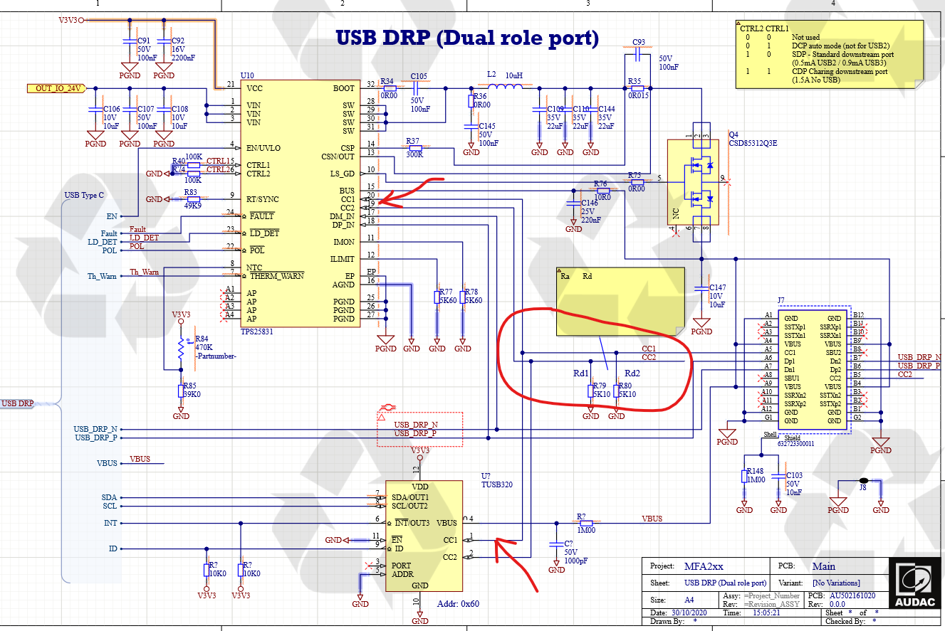
Now we are going to connect this port with a USB type C connector.
The USB C acts as the host and device.

In host mode, we need to supply a voltage of 5V with a current from 1 to 1.5A on the device.
In device mode, the 5V from the external host is not used to power them.

See attached file for more details.

I use a TPS25831 to power the device.
We use the TUSB320 to automatically switch from host to device.

The CC1 and CC2 pins are used on both components.
Can we use these pins in parallel?
How should we configure the CTRL1 and CTRL2 pins?
Must the pins DM_IN and DP_IN of the USB C connector also connected to the tps25831?

If there is any other comment with the drawings you can always let me know.

Regards

  • Hi ,

    The DP_IN and DM_IN of the TPS25831 is mainly used for DCP auto charging function which have including the apple divider 3 (2.4A) mode and Samsung mode .If you focus on data communication you better chose TPS25830-Q1 or you can choose 831 but don't connect the DP/M to DP/M_IN pin .   

    I check your schematic, the TPS25830/1-Q1 is an DFP device , so when there have Rd in the CC1/2 the 831 will be active and supply 5V output. However , you can set the CTL1 and CTL2 to 00 to turn off the external FET Q4 (cut off the 831 5V output ) when you want 831 work as a device. 

    The main concern is there are two current source for CC line , once is broadcast  from 831 the other is come from the host. This  two current source will finally get the voltage equal to 2*ICC*Rd which will make the voltage out of 831 CC1/2  pin detect windows. 

    The solution here is 831 work as Source/UFP and external type C device work as Sink/DFP. That will not require the TUS320 here but the external type C device should support PD protocol. 

  • Hi,

    I have change my design. see below.

    But how i can now detect the DCP and UFP mode (host or device). 
    My CPU has a ID pin to detect the host / device direction.

  • Hi,

    You design is type c port but not type A port , in the type A port there will have a ID pin set low for host or floating for device. 

    To my understand, your Soc should support OTG , which can process the HNP and SRP protocol. 

    You can through the DP/M to negotiate with the external device for data role swap.

    When you swap the host/device, you should cut off the TPS25831-Q1 output through external FET , you can set CTL1/2 to 00 to do that. 

  • Hi,

    The datasheets describe when we set CTL1 / 2 to 00 that this is a RESERVED option, and DO NOT USE it.

    Can you provide us with more information about this?

  • Hi,

    I am sorry. I am not very sure the VBUS should cut off or not during the role swap.  You may use C to A cable or C to C cable

    In the type C port it can work as Source/UFP then it don't need to cut off the power from TPS25830-Q1. A Notebook Docking is a example (power to Notebook , and work as a UFP) . 

    The CTR1/2 make to 00 and 01 is reserved option , as type C port will not need cut off the VBUS using external FET.

    You can refer to TPS25840-Q1 datasheet page 35 -table 6. This table logic is same as TPS25830-Q1