This thread has been locked.

If you have a related question, please click the "Ask a related question" button in the top right corner. The newly created question will be automatically linked to this question.

TUSB1064RNQEVM: TUSB1064RNQEVM DP don't work and development steps

Part Number: TUSB1064RNQEVM
Other Parts Discussed in Thread: TUSB1064, TPS65982

Hello TI team

1.I want to use the TUSB1064 chip in my application , so I buy one TUSB1064RNQEVM but  there is some problems need help .

a). When I use default configure the USB 3.0 work well ,but  the DP isn’t .

b). The host is Macpro book, I think it can work 2lane + USB3.0, but I don’t know TUSB1064 whether config 2 lane by

 default config.

c). The source 2lane + TUSB1064 2lane + sink 2lane, or The source 4lane + TUSB1064 4lane + sink 4lane

 just above config can work well, so how to config the TUSB1064 4lane?  The sink is DP to DVI cable, so I don’t exactly know it work 2lane or 4lane, so I need to config TUSB1064 2lane or 4lane.

Can you give more information to use the TUSB1064RNQEVM. I had collected some information from ee-forum, but still not get the clear development steps.
  • hello  TI  team

    1. It didn’t find the TPS65986 data sheet from www.ti.com , S Can I reference the TPS 65982 data sheet?

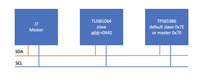
    2. JMP4,JMP6 select the TUSB1064 I2C device address.  default config are A0=R,A1=R,slave addr=0X42.

    3. SW1 select the TPS65986 I2C device address. default config is PIN F1 float slave addr=0X7E.

    4. J7 is the communication interface to config the TUSB1064 and TPS65986 devices.

    5. JMP7 is the config the TUSB1064 I2C or GPIO, default is GPIO, so it need change the jump to select I2C enable.

  • 6472.Archive.zip

    I don't know why can't communicate the TUSB1064 by default I2C address 0x42, and remove jumps A0/A1 address 0x24.

    attached is the picture that EVM config and communicate wave form.

  • when A1, A0 is R,R I2C address is 0x, not 0x4221

  • Hi,

    I recommend having I2C_EN,. A0 and A1 pins pulled high to allow the PD controller to configure the TUSB1064 at connection. Can you read the register 0x00 from device address 0x0F when these pins are pulled high?

    DP mode is not configured by default and 2 lane vs 4 lane operation will be determined by PD controller negotiation. You can configure TUSB1064 for 4 lane DP mode by modifying register 0x0a CTLSEL[1:0] bit to 0x3. Keep in mind during manual configuration you will need to ensure FLIPSEL bit matches the actual connection (this is normally handled by the PD controller). 

  • Hi Malik

    Thank you for your answer !

    1. It didn’t find the TPS65986 data sheet from www.ti.com , So can I reference the TPS65982 data sheet?or can you shear the document.

    2. I want the EVM work at USB3.0 + 2 lane or 4 lane, Can you brief description how to step up?

    3. I had change the EVM config, Use JMP8 PIN1&2(I2C interface) to config TUSB0164 alone.

    DP mode is not configured by default and 2 lane vs 4 lane operation will be determined by PD controller negotiation.

    >> this mean that if expect the host output DP signal should program DP device first, The default PD program didn't contain DP alternate config. Is that right?

  • Hi,

    1. I do not have this document to share.

    2. The on board PD controller should be able to configure TUSB1064 for the negotiated link. The PD controller works with only on I2C device address 0x0F. If EVM setting are changed from default setting PD controller will not be able to configure TUSB1064. 

    3. DP mode is nor configured by default, PD controller will configure the device via I2C based on the negotiated connection. If you use TUSB1064 is a different mode ensure it is power separately from VBUS. Configure the device. Then plug in the desired connection. DP alternate is negotiation by the PD controller at the initial connection, If the link is able to negotiate this mode and TUSB1064 is already in the correct mode then you should see working links. Recall that TUSB1064 is for DP sink applications only. 

    Correct or PD negotiation did not commence for a DP alt mode link. You can tell if you have access to a USB-C analyzer. 

  • Hi Malik

    Sorry to late reply your message because the vacation .

    1.I am  capture J7( PIN1 & PIN 3) but there were any wave form.

    2. The PD controller works with only on I2C device address 0x0F.

    >>So  this mean the TUSB1064 device address must be 0x0F, is that right?

    3.According  to your describe, does it mean configure theTUSB1064 correct mode first. Then plug in typec connector , and the PD controller  will negotiated make the host enter DP alternate ?

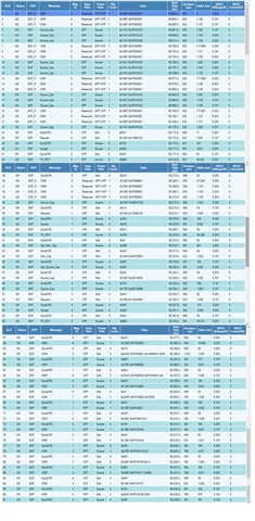
    below is the PD log file 

    pd log file.zip

  • HI,

    2. Correct, looks like your A0 and A1 pins are not pulled up to VCC (from the board photo) Can you try pulling them up?

    3.Correct. In the log I do not see any PD negotiation for DP alt mode. Is this log complete? What Type-C device are you using to test and have you confirmed d it has DP alt mode function (sanity check)?