This thread has been locked.

If you have a related question, please click the "Ask a related question" button in the top right corner. The newly created question will be automatically linked to this question.

TUSB1064RNQEVM: Not able to get DispalyPort working on TUSB1064RNQ EVM Dev board

Part Number: TUSB1064RNQEVM
Other Parts Discussed in Thread: TUSB1064, TPS65982

I'm working on a USB-C to DisplayPort design with the TUSB1064 chip and ordered the TUSB1064RNQEVM board for testing but having issues getting it to work. I've tried setting all the defaults as shown in table 1 of the eval board users guide but the board is still not outputting anything onto the display. I've tried using a few different USB C video inputs to the board including a few phones, MacBook and a PC bus still not getting anything to work. When connecting to a PC to input video into the dev board USB-C connector, the PC was able to detect it as a potential monitor but shows an error with an issues with the connected device.

Also changing the CTL1 and 0 lines to change the type of output does help with getting an output out of the DisplayPort connector.

I would appreciate some help to get this chip working and integrated into our design.

Not sure if it's a faulty board or something not set right on it.

  • Hi,

    Lets start by putting device into I2C mode so on board PD controller can configure TUSB1064 at the time of connection. This also prevents mismatch between what tUSB1064 is configured for and what is connected. If you have external I2C master you can help verify I2C bus working and will help debug faster than GPIO mode.   

  • Ok, reset everything back to table 1 defaults which includes enabling I2C with I2C_EN=high. Still nothing on the display output. For using a I2C master i'm assuming we can request the IC state or what its detecting on the USB and DP side with some kind of commands? is there specific commands to send to it to request the data? As for using an external I2C master, i don't have a dedicated one but thinking i could possibly use an Arduino to decode and send/receive data to PC over usb.

  • With the external I2C master can you read the DEVICE_ID registers from TUSB1064? Are you using an external power supply? Please make sure that A0/A1 are pulled up appropriately. An Ardino should do just fine.  Correct using an I2C master you can directly control the TUSB1064 state. 

  • Hi Malik, so i got a USB-ISS device instead for using as a I2C master and wasn't sure about the commands to send. I couldn't find a DEVICE_ID register in the TUSB1064 datasheet. also what address would i use to address this IC? Do you have a whole hex command example i can send to it to read the state, with address, register r/w?

  • Hi Nikolay,

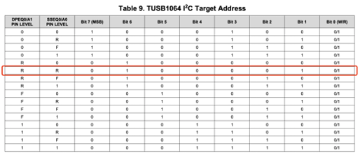
    TUSB1064 has many I2C address that can be configured from the SSEQ0/A0 and DPEQ0/A1 pins. Table 9. TUSB1064 I 2C Target Address will give you the 7 bit address to be used. It will be easiest to place the part in I2C mode via I2C_EN = 1 and leave A0+A1 in there default positions (pulled up, pin 2-3 connected) to use address 0x0F (7bit address). You should be able to read register 0x00.

  • Sure I can take a look.

  • Not getting any response to any commands. I tried reading from a few different addresses: 0x0F, 0x1F but still no response even when trying to read from registers 0x00, 0x0A and a few other registers shown on the datasheet. 

  • Hello Nikolay

    1. If you remove R41,R44. then soldering R3,R5 and other is keep default config . I think you can use 0x42 device address to communicate with TUSB1064 chip. Concurrently you can use 0x7E device address to communicate with TPS65986 chip.

  • What re the voltages on the following pins:

    • Vcc
    • SSEQ0
    • DPEQ0
    • SDA
    • SCL
    • I2C_EN

    Are external I2C pull-ups being used? 

  • SSEQ0: 3.29
    DPEQ0: 3.23
    SDA: 3.29
    SCL: 3.29
    I2C: 3.29

    Sys_POWER to gnd:4.38
    vbus to gnd : 4.38

    Yes, the I2C master I'm using has 4.7k pull-up. The measurements take above where with the i2c master disconnected.

  • Can you disable the PU resistors in your I2C master? Are R76 and R78 populated?

  • Hi Malik, I was able to get the board working in i2c mode and got DP and the USB port working. I think the issue was that i had the ctl0, ctl1, flip jumpers installed while trying to get i2c mode working. From the schematic it looks like those jumpers short out the i2c bus and should not be installed. Table 1 on the eval board users guide is a bit confusing since it says to use jumpers. Another issue I found caused it not to work was that standard usb c phone cables did not work since some of the pins are unpopulated so caused it not to work since DP+USB mode requires all 4 lanes. Used a thunderbolt 3 cable and it worked.

    I still was not able to get it to work in GPIO mode thought which im not sure why it didn't work.

    One thing i was curious about this USB-C circuit was getting it to supply power to the upstream facing USB C device to charge it. Currently there is a diode (D1) installed near the USB C connector to not allow current to flow to the device and charge it. Would the TPS65982 IC used on this board work for this purpose? or are there any other IC's you would recommend for this application? From what i found about TPS65982 it also need to be programmed before it'll work, is there another PD solution that would does not need to be programmed?

  • Glad you were able to get this working! Looks like the users guide needs to be update here. GPIO mode should work since I2C mode worked as well. I would ensure the FLIP pin is the appropriate state with regard to the cable orientation, this could be the cause for confusion. I am not a expert on TPS65982  but it should be able to service your needs for a power role swap although it will need to be programmed to do this. 

  • Could you provide pointers to any reference designs for the TPS65982 used together with TUSB1064 (or a really similar IC) for the design integration? To help with the design time and reduce compatibility issues.

    Also is the TUSB1064 compatible with USB-C PD IC's from other manufactures? if using it in the i2c mode where the IC's from two different manuf. chips are connected together like on this dev board? 

  • I do not believe a reference design exists today with both devices but if you are using TPS65982 or some other PD controller using I2C mode this will help to reduce circuit complexity. TUSB1064 will then be controlled completely though I2C and will allow for faster design and debug since the only change require will be in the PD controller FW. In the case of TPS65982 there is a GUI to help facilitate this process. 

    TUSB1064 does not have any know restriction with non-TI PD controller on the market. I2C should work regardless of the PD controller.