This thread has been locked.

If you have a related question, please click the "Ask a related question" button in the top right corner. The newly created question will be automatically linked to this question.

Problems with 3V3 CAN Tranceiver SN65HVD232 / SN65HVD235

Other Parts Discussed in Thread: SN65HVD232, SN65HVD235, CC2520, MSP430F5438A, SN65HVD255

Hello,

I need to implement the functionality of "sending out a single CAN-Message to other nodes" if a boolean state changes on my PCB.

Overall number of nodes at the bus will be 3-4. Bus-Speed is fixed at 100kbps/125kbps .

I am using a MCP2515 Controller with an TI SN65HVD232 3,3V CAN-Transceiver. Later I switched to SN65HVD235 because I needed CAN-H and CAN-L to withstand +/-15V.

Unfortunately I had trouble with both 3V3 Transceivers.

I'm sending out CAN-Messages in an endless loop and watching CAN-H and CAN-L on a scope (no nodes attached to the bus):

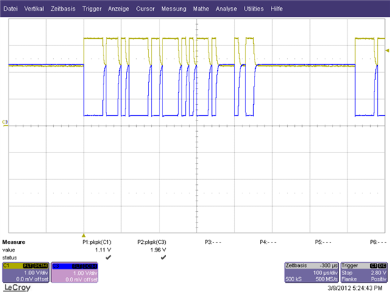
My problem is, that CAN-H / CAN-L seem to be very sensitive and cause the bus to break down (even if nodes are attached).

- While I touch CAN-L the signal is breaking down (and causing the CAN Bus to not work any longer).

- If I add 120R to close the network the signal breaks down too.

- Even adding D8/D9 make the signal break down.

While touching CAN-L:

I don't know what is wrong, but surely something is.

I am new to CAN and dont know where to start searching the problem. The other nodes signals (with 5V Tranceivers) are looking very stable even while touching the signal lines. What am I doing wrong ?

  • Tobias,

    1) Try to replace transceivers and see whether the problem remains.

    2) Check your ground connections. When the slightest leackage currents (through you or the diodes) can cause this type of signal collaps, I suspect something in the supply   path is not conducting properly.

    That's all I can come up with for the moment. Pleae let me know how it works out.

    Regards, Thomas

  • You have properly terminated your CAN bus correct?  Should have a 120 ohm termination resistor at both ends of the network, this is also necessary to keep the dominant to recessive edge timing correct.  You can refer to section 4, and sub section 4.5 of the application note SLLA270 on www.ti.com for some basic information on termination of CAN.   If you are just running a test of a single node without a network you need to terminate with 60 ohm load to emulate a network loading of the two 120 ohm termination resistors in parallel. 

    In case of the HVD235 what resistance are you using on Rs pin?  Does the slew rate chose allow the data rate you are trying to run? 

    The diodes you have chosen are not a standard method for CAN.  Are you trying to protect the device from ESD / transients?  Try removing them. 

    -- Scott

  • Thomas Kugelstadt said:

    1) Try to replace transceivers and see whether the problem remains.

    2) Check your ground connections. When the slightest leackage currents (through you or the diodes) can cause this type of signal collaps, I suspect something in the supply path is not conducting properly.

    I replaced the CAN-transceiver (and the controller) 3-4 times without any success. I tried an different PCB as well.

    The 3V3 power supply is also used by an MSP430F5438A and an CC2520 which are working well on the board. GND is used as fill-up polygon on TOP and BOTTOM of my 2 layer PCB and should be connected properly to the device pins. Maybe i have to add some kind of 100nF or a stabilisation cap to the Vcc pin of the transceiver ?

    Scott Monroe said:

    You have properly terminated your CAN bus correct?  Should have a 120 ohm termination resistor at both ends of the network, this is also necessary to keep the dominant to recessive edge timing correct.  You can refer to section 4, and sub section 4.5 of the application note SLLA270 on www.ti.com for some basic information on termination of CAN.   If you are just running a test of a single node without a network you need to terminate with 60 ohm load to emulate a network loading of the two 120 ohm termination resistors in parallel. 

    In case of the HVD235 what resistance are you using on Rs pin?  Does the slew rate chose allow the data rate you are trying to run? 

    The diodes you have chosen are not a standard method for CAN.  Are you trying to protect the device from ESD / transients?  Try removing them. 

    What I know about termination is that every device at the end of the bus have to add 120R between CAN-H and CAN-L to prevent reflections, but If i add 120R at my 3,3V node the CAN-Bus communication will break down. I tried split termination as well. If the other nodes are terminating CAN will work (except for my problem). The cables I use for each device is only about ~30cm long. I will test adding 60R in single testing mode.

    Thx for the app note, i will read into it tomorrow.

    I tested the slope of the HVD235 with Rs = 0R, 100R 10k and 100k (to GND). Data looked OK (as above in the picture) at 100kbps with all these Rs combinations, but the problem remains.

    The TVS diodes were added as safety option and are not populated right now. If I populate them the device will not (allways) work correctly.

    --- sorry for my terrible english skills by the way :-) ---

  • Tobias,

    definitely you need to buffer the Vcc of the CAN transceiver. Especially when using a 2 Layer PCB. In this case yur ground plan can have higher inductance and any switching of the outputs will compromise the Vcc of the transceiver. Try a 100nF to 220nF and measure again. These caps also help protecting the transceiver against bus noise by bypassing any transients on the bus to ground.

    regards, Thomas.

  • You may want to go as high as 1uF for the Vcc bypass and local supply decoupling.  CAN switches in the dominant state to about 60-80mA fairly quickly so you want to have a lot of local energy stored to make sure the transitions aren't starved.  We use 1uF local bypass cap on our test boards.

    You may also want to look at the user's guide to the SN65HVD255 CAN EVM.  It has many generic hints in terms of CAN circuitry that apply not only to the 5V CAN transceivers but also the 3.3V CAN transceivers.

    -- Scott