


Good day, colleagues,
My customer is testing our digital isolator ISOW7841 in configuration 3.3 V to 3.3 V.
Pin SEL(10) is directly connected to the ground plane.
Input caps: 220 µF + 10 µF + 0.1 µF.
Output caps: 0.1 µF + 10 µF + on board 6 x 10 µF + 56 µF
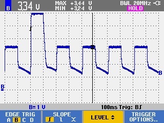
During the testing output voltage of ISOW7841 was 6V in some cases.
They made a set-up for automatic collection of statistics with the following algorithm:
1) supply power to ISOW7841
2) waiting for the voltage to be settled on the output 100 ms
3) measure the output voltage
4) turn off the power from ISOW7841
5) delay for the reclosure ( they tried different delay from 20ms to 1s, output caps have time to discharge to different voltage levels)
6) go to step 1
They tested 4 chips and sometimes output voltage on the isolated side of ISOW7841 was 6V.
The results of measurements of the output voltage (point 3) were collected in the form of a histogram:
Chip №1, delay for the reclosure is 100 ms:
V, amount
0, 0
1, 0
2, 0
3, 999
4, 0
5, 0
6, 1
7, 0
8, 0
9, 0
Chip №2, delay for the reclosure is 100 ms:
V, amount
0, 0
1, 0
2, 0
3, 934
4, 0
5, 0
6, 66
7, 0
8, 0
9, 0
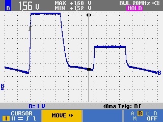
For further tests , the 56 μF capacitance was removed from the output and the output was additionally loaded with a 360 Ohm resistor. Failure appeared less often, but is still presents.
What could you recommend? The circuit should always supply 3.3V.
Thank you,
Daria
