This thread has been locked.

If you have a related question, please click the "Ask a related question" button in the top right corner. The newly created question will be automatically linked to this question.

ISOUSB211: device is not working if using type c USB connector.

Part Number: ISOUSB211

Hello TI experts,

my customer made their own PCB with ISOUSB211, and I asked some questions like below link ;

https://e2e.ti.com/support/isolation-group/isolation/f/isolation-forum/1077648/isousb211-isousb211-does-not-working-on-customer-s-pcb

and they tested more with several different methods.

please see the picture below first.
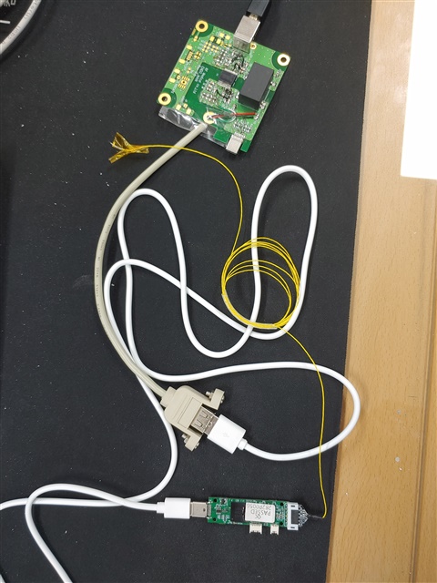
at first they designed USB type C connector on downstream port because the module is connected by type c connector.

but they could not succeed with their PCB.

so they tried to change type C connector to type A (gray cable) -> using type A to type C cable (white cable) -> and finally connect the module. finally they succeeded with this configuration.

I don't understand that they used only USB 2.0 signals although they used type C connector. and I think there is no problem with it.

Could you check the schematic(in previous thread) and this method of connection again to solve this problem?

and I have another question, the temperature of ISOUSB211 goes up to 57 degree when it is working.(they used infrared thermometer) they feel very hot when they touch ISOUSB211.

is it normal situation?

(when they use power supply instead of USB 5V power, it consumes only 170mA.

if this kind of heat is normal, should I consider heat sync for cooling the device? or should we modify artwork for better cooling? (but I could not find thermal pad on ISOUSB211.)

please check these 2 issues. Thanks.

Best regards,

Chase

  • Hi Chase,

    Thanks for reaching out and for sharing an update.

    Could you check the schematic(in previous thread) and this method of connection again to solve this problem?

    In the previous discussions, there are have been multiple suggestions made to make changes in the schematic. Could you please confirm if the suggested changes were implemented?
    If they are implemented, please do share the updated schematic for us to review and confirm if everything is fine.

    and I have another question, the temperature of ISOUSB211 goes up to 57 degree when it is working.(they used infrared thermometer) they feel very hot when they touch ISOUSB211.

    is it normal situation?

    Could you please also confirm the speed at which device is being operated? LS, FS, or HS?
    If the schematic is not updated and internal LDOs are connected in series, then it can heat up device significantly. Please share schematic to review. Thanks.


    Regards,
    Koteshwar Rao

  • Dear Koteshwar,

    Thank you for your support.

    Here is a good news, they finally succeeded to get it working.

    but still there is a problem, the temperature of ISOUSB211 is about 70℃ when it's working.

    I attach a latest schematic. please review it for any problems about this high temperature.

    also the speed of module is high speed. please also check it.

    + one more question, what is the purpose of the EQ pin exactly? I just knew that I have to pull-up or pull-down each EQ pins depends on the length of USB cable. Am I right?

    Best regards,

    Chase

  • Hi Chase,

    I'm glad that your customer has identified the root-cause and got it to work.

    Regarding the operating temperature let's walk thru the math to confirm the observation.

    MaxDeviceTemp = MaxDevicePower * ThetaJA + MaxAmbientTemp   --- (1)

    Based on the given current of 170mA and the power supply of Vbus and Vcc is 5V, 

    the MaxDevicePower is 170mA*5V = 0.850W. The measured MaxDeviceTemp = 70C

    Using (1),    MaxAmbientTemp = MaxDeviceTemp - MaxDevicePower * ThetaJA

                                                      = 70 - (0.85 *51)     ThetaJA is listed on page 6 of the datasheet

                                                      = 26.65C.

    The calculated ambient temperature is 26.6C and it is within expectation.

    Hence, with this configuration the device temperature of 70C is reasonable.

    Section 9.3 in the datasheet provides different configurations to meet different thermal considerations/requirements.

    The main idea is to reduce the maximum power dissipation of the device and thus reducing the device temperature.

    I suggest lowering the Vcc to around 3.3V by adding a resistor between the 5V supply and Vcc pin. (Please refer to page 31 of the datasheet)

    Assuming that 20% of the current is consumed by Vbus and 80% is consumed by Vcc, 

    the MaxDevicePower = 5V*34mA + 3.3*136mA = 0.449W.

    Using (1):  MaxDeviceTemp = 0.449*51 + 26.65 = 49.5C.  

    Hence, the device is 20C cooler.

    To calculate the resistor value, assume the worst-case current consumption for Vcc is 96mA. 

    Resistance =  5V-3.3V/96mA = 17.7 ohm. 

    The EQ pins set the equalizer of the repeater receiver and the pre-emphasis of the repeater transmitter.

    They are used to compensate for the channel loss and enhance signal integrity when a system has high channel loss.

    Please refer to this application note for the details.

    Regards,

    Alfred

  • Hi Chase,

    Please also advise the customer to move the capacitors close to the pins and follow the guideline stated in the datasheet.

    Regards,

    Alfred

  • Dear Alfred,

    Thank you for your support.

    I said that my customer succeed to connect the module using ISOUSB211, but there is still problem.

    the possibility of connection is about 50%. it means that when they try to connect toe module 10 times, they succeeded 5 times and failed 5 times.

    and even they succeeded to connection, connection fails again if they try to execute other function (like changing settings or measure something, etc.)

    anyway, the connection is very unstable. and they tried to test all the combination of EQ pins, it did not work at all.

    could you check the way to improve the connection? and please let me know if you need more information about it. Thanks.

    PS:: the routing from IC to host connector is about 60mm, and from IC to peripheral is about 30mm. could it be a problem? how about differential impedance matching of USB routing?

    Best regards,

    Chase

  • Hi Chase,

    Thank you for reaching out to us again!

    The first step is to rule out the type-C connector is the root-cause.

                1. Did it only happen with the type-c connector?

                 2. If you use the type A connector, are you still seeing the same issue.

    The second step is to check the power integrity and make sure the the voltages for VBUS, V3P3V and V1P8V are within requirements.

               1. What are the voltages for the good and bad cases?

                2. When the system does not connect, was there a huge current spike? 

    The third step is to probe the differential signal and check the signal quality.

               The routings (6cm and 3cm) are relatively short and low loss and hence EQ might not help in this system.

               The differential impedance is recommended to be 90 ohm.

               If the impedance deviates significantly, it can result in huge reflection and degrade signal integrity.

    Regards,

    Alfred

  • Hi Chase,

    Do you have any update?

    Regards,

    Alfred

  • Dear Alfred,

    My customer is still testing what you mentioned.

    I will send you the results asap. Thanks.

    Best regards,

    Chase

  • Thanks Chase! I