This thread has been locked.
If you have a related question, please click the "Ask a related question" button in the top right corner. The newly created question will be automatically linked to this question.
Dear Team
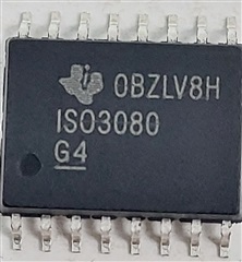
Please help me find out whether the attached image of ISO3080 is a genuine TI product or a counterfeit.
We are facing a serious issue during production the New variant of chip we bought recently is not performing as expected, the earlier chips we have has no issue.
We found the Logo on the new chip is different and text are printed not engraved.
Thanks
Ranjit Singh Laishram
IIT Madras
Hi Ranjit,
Thanks for reaching out.
To check if the part you have is a genuine TI part or a counterfeit, please follow the guidelines provided at the below link and submit the requested information to Customer Support Center.
In the meantime, please share more details related to the failure you are observing so that we can comment if such a failure is expected from a genuine TI device. Please also mention how many new suspect devices have been tested and how many are failing. Thanks.
Regards,
Koteshwar Rao
Hi Koteshwar
We found problem on around 63 boards, We observed that the R out is always LOW in the new chip while working chip will have High after the power up
Please find attached waveform of working and non working boards.
Here Blue line for R and Yellow line for D.
Kindly help if you need any more info please let me know.
Ranjit
Hi Ranjit,
Thanks for sharing additional information.
Could you please share the schematic so that I can review and make sure there is nothing wrong in the schematic?
Could you please also confirm if what is the VCC1 supply ramp time that you use? i.e., what is the time does VCC1 take to go from 0V to its final voltage? If possible, please also include VCC1 along with D and R and show a power-up waveform. Thanks.
Regards,
Koteshwar Rao
Hi Koteshwar
Please review our schematic, Wh have the option to switch the uC_5V to either 5V or 3.3V but by default to 5V the isolated 5V supply is generated by using SN6501DBVR a Transformer and LP2992..
The VCC1 Ramp time is around 5mS. We have tested with both 3.3V and 5 V on the logic side
For New Batch Chip R(Blue line is always LOw) VCC yellow
With and old Batch Chip R(Blue line Goes High) VCC yellow
Regards
Ranjit Singh Laishram
Hi Ranjit,
Thanks for sharing the schematic and waveform.
The schematic looks good and I didn't see any major concerns. Since the VCC2 requires higher current to drive the RS-485 bus, we recommend that an additional capacitor of 1µF or 10µF is added to the existing 0.1µF cap.
For the R output to go HIGH upon power-up, RE\ has to be LOW otherwise, R stays in Hi-Z and it can be read as LOW by oscilloscope. Please confirm if RE\ is being made LOW during power up.
I also see that R output for the second waveform is not 5V and rather it is showing up to be around 3.3V even when VCC1 is 5V. Could you please recheck your test setup to see why you are seeing a 3.3V on R when 5V is expected?
If you do not see any issues in the test setup, then it maybe best to verify that these parts are genuine TI parts. To do so, please follow the suggestions I had provided earlier on how to check the genuineness of TI parts. I am copying the link below for your reference again. Thanks.
Regards,
Koteshwar Rao
Hi Ranjit,
I hope all the inputs provides above are helping you address the issue. If they didn't, then, as recommended, please follow the guidelines provided in the link I have shared to check if the parts are counterfeit.
I will go ahead and mark the post as closed. If you have any further updates after following the anti-counterfeit guidelines, you can reach out to us by either responding to this post or creating a new one. Thanks.
Regards,
Koteshwar Rao