- Ask a related questionWhat is a related question?A related question is a question created from another question. When the related question is created, it will be automatically linked to the original question.
This thread has been locked.
If you have a related question, please click the "Ask a related question" button in the top right corner. The newly created question will be automatically linked to this question.
Hi team:
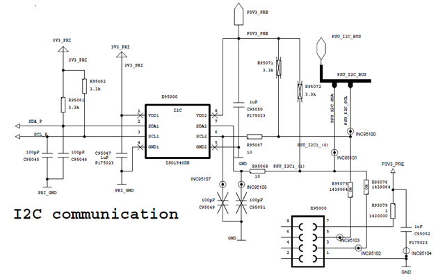
can you help review the schematic for ISO1540?
The application is used Master to communicate with Hotswap controller (slave), but the reference ground is different.

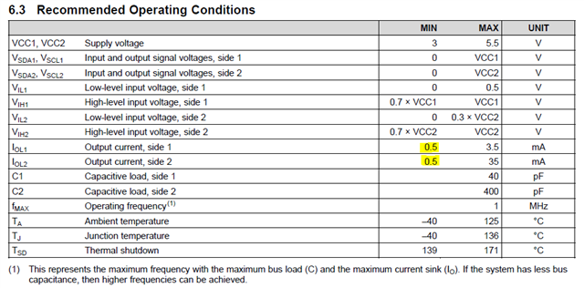
During check DATASHEET recommend condition, we found Side1 IOL1 and IOL2 was proposal min is 0.5mA. and C1 Capacitive load side1 is 40pF max. which is not aligned with the schematic above. But we didn’t got fully understand why the recommended is like this, and how to calculated these. can you also help explain why we need to choose such value? Thanks

Hi Kelly,
Thank you for reaching out.
The schematic looks mostly good except for the capacitors on the bus. Any reason why customer wants to use 100pF capacitors on the bus?
Please also make sure the input/output thresholds of Side1 of ISO1540 and the device it is connected to are compatible by verifying the specs in their respective datasheets.
During check DATASHEET recommend condition, we found Side1 IOL1 and IOL2 was proposal min is 0.5mA. and C1 Capacitive load side1 is 40pF max.
I believe you are asking why there is a minimum current recommendation in the datasheet. Please note that the minimum current indicates a maximum pull-up resistor you can use. i.e., for 3.3V supply, the maximum pull-up resistor that you can use is 6.6kΩ. If a higher resistor is used then it would increase the rise/fall times restricting the device to be used for lower datarate than it is rated for. If the recommendations are followed, then you will be able to meet the device supported datarate of 1MHz.
The maximum capacitance on device pins indicates the maximum number of nodes it can be connected to. Typically the input capacitance of I2C pins of most devices is going to be about 10pF and worst-case 40pF. This indicates that Side1 of ISO1540 is meant to be connected to only one device while Side2 can be connected to multiple nodes. The max number of nodes that can be connected to Side2 depends on the pin capacitance of each node and the bus capacitance. The total capacitance on Side2 pins shouldn't exceed 400pF as stated in datasheet.
This is briefly explained in the below FAQ.
I hope this helps you with the reasoning for the values in recommendations. Thanks.
Regards,
Koteshwar Rao
hi Koteshwar,
Currently we will use 100kHz as the I2C communication frequency, no more higher data rate needed.
So what will be the allowed highest C1 Capacitive load /pull up resistor value if maximum 100kHz communication frequency used?
BTW, the bypass capacitor for the 3.3V power supply is 1uF in circuit, is it ok to use? What is your suggestion value on this? Is this capacitor for decoupling filter and providing energy purpose when I2C communication?
thanks.
Hi Kelly,
Thanks for sharing additional inputs.
The maximum allowed load capacitance doesn't directly depend on the datarate rather it depends on the number of nodes connected on the bus. As recommended in the datasheet, please make sure the total capacitance doesn't exceed 40pF on Side1 pins and 400pF on Side2 pins.
Since device performance is guaranteed with a minimum output current 0.5mA, I would recommend to keep the pull-up resistors <6.6kΩ. You can use higher values if you would like but I do not believe there is any major advantage by using higher pull-up resistance.
Hence, the values I recommend for pull-up resistors is 3.3kΩ which you already have. For load capacitance, I recommend not adding any capacitors on I2C bus pins.
Regarding decoupling capacitors, sorry I missed to notice that the decoupling capacitors that you have used are 1µF in value. As recommended in the datasheet, we suggest you to use 0.1µF as decoupling capacitors. These values make sure they provide the transient currents needed by the device.
I would also like to mention that ISO1540 is an older I2C isolator. recommend that you use our latest generation I2C device, ISO1640, which is pin-compatible with ISO1540 and offers much better performance.
Let me know if you have any other questions, thanks.
Regards,
Koteshwar Rao