This thread has been locked.

If you have a related question, please click the "Ask a related question" button in the top right corner. The newly created question will be automatically linked to this question.

ISOW1412: Questions on Schematic and Layout

Part Number: ISOW1412

Hello team,

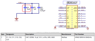
1. Capacitor value

On EVM, a Murata cap is applied as C4. Do we have some recommendation on DC bias and initial tolerances? Also is there a lower limit?

*C4: GRM21BR6YA106KE43L (+/-10% Initial Tolerance, -37.3% DC Bias (@5V))
10uF x (-10%) x (-37.3%) = 5.6uF
2.  13.1 Layout Guidelines

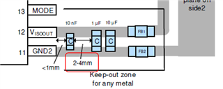
It says no traces or grounding within 4 mm, is this origin recognized from copper to 11pin, 12pin?

If a 4 mm circle is added to the EVM layout, why would there be a pattern inside the circle around L5?

3. 13.2 Layout Example

What is the reason for the 2-4mm limitation between capacitors?

If the passcon is moved away from the power supply pin, it may affect the stability of the power supply. What happens if the passcon is moved closer to the power supply pin? 
Best regards,

Shotaro

  • Hi Shotaro-san,

    Thank you for reaching out.

    You probably missed to attach the schematic, so I am not sure which ones are C4 and L5 but I will still be able to answer your questions. Please find my inputs below,

    1. There are no specific requirements by ISOW1412 on the decoupling cap.
      1. The 0.01µF and 1µF caps provide the necessary transients required by ISOW1412 while the additional 10µF is a bulk cap for maintaining a steady supply to device. The variation of 10µF shouldn't affect device device operation, customer can choose the the tolerance they prefer.
      2. I couldn't locate -37.3% DC bias information in datasheet, could you please confirm where exactly you saw this information?
    2. This is referring to the keep-out zone draw in the example PCB layout diagram. It is reiterating that keep-out zone should be followed and no other external traces or planes should lie in this region.
    3. The spacing of 2-4mm between the capacitors enables slightly better efficiency and lower emissions due to better noise filtering. If possible, we recommend that this is followed. But if now followed, the impact on efficiency and emissions will be negligible.


    Regards,
    Koteshwar Rao

  • Hi Rao-san,

    Thank you for supporting.

    I think that the DC bias information comes from the below URL.

    https://www.murata.com/en-global/products/productdetail?partno=GRM21BR6YA106KE43%23

    Best regards,

    Shotaro

  • Hi Shotaro-san,

    Thank you for sharing the link, this helps.
    This behavior is similar for most capacitors and hence, this is okay. Thanks.


    Regards,
    Koteshwar Rao