This thread has been locked.

If you have a related question, please click the "Ask a related question" button in the top right corner. The newly created question will be automatically linked to this question.

ISO1042: ISO1042

Part Number: ISO1042

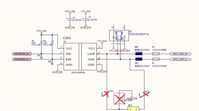
we are using this IC for our CAN network as improved design in our product but we are facing issues at site when multiple node (currently 24 nodes) connected.

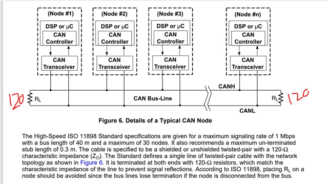
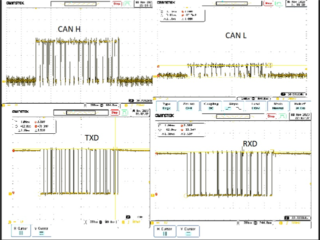
This IC CAN H and L acros resistance value strat to reduce and cause whole CAN network colapse. we used to test our prototype with  max 4 node with short distance no issue with 120ohm end resistor in end of network.

what cause CAN H to L resistance to drop after some times?. is it tranceiver wont support multiple node and long distance?. how to improve this resistance drop.

Can get contact number from technical supp ort to come and take a look in our offcie.  

  • Hello Latha, 

    Thanks for reaching out and for using ISO1042. The schematic is blurry, so I can't make out any details, however it looks like there are not any termination resistors used on the CAN bus.  If the cable length between nodes is long this may also affect the maximum number of nodes the CAN bus can support as you suspected.

    Please see 9.2.2.1 Bus Loading, Length and Number of Nodes. For a large CAN network with many nodes, bus parasitic often limit the maximum number of CAN nodes. Careful design and termination resistors can help extend the number of nodes supported (see 9.2.2.2 CAN Termination).  

    The following app not on CAN Physical Layer Requirements (ti.com) (Section 4) as well as Top Design Questions about Isolating CAN Nodes Bus Design (Rev. A) provide some good insights and on termination as bus characteristics as well. 

    Best,
    Andrew

  •  CAN BUS.pdf

    Hi Here attched Schematic CANBUS network follow as highlighted in section 4

  • Hello Latha, 

    The amount of CAN nodes a bus can support is severely limited by cable lengths and signaling rate. The components marked with a red 'X' (and JP4 1-2 connected) are needed to for a split termination configuration. Operating without termination resistance (single or split) would be a possible reason the CAN bus is not communication. 

    The following snip taken from section 4 is also relevant if your application has a long stub length (>0.3m).

    What is the cable length and signal rates for your application? Do you have scope captures from TXD and RXD to CANH and CANL? 

    Best,
    Andrew

  • we follow as below.

    stub length around ~.3 to .4m

    cable length overall network around 150meter and CANBUS speed 100kbps for 24 nodes

    Damaged IC Screenshot

    Good IC screenshot

  • Hello Latha, 

    Two 120-ohm termination resistors shown above is sufficient. However, the "Good IC" looks like the CANH and CANL are not differential which suggests some error in the termination network. Please confirm that the second CANH and CANL captures are the same voltage-per-division on the scope. 

    Best,
    Andrew

  • bad IC-CAN H and CAN L show voltage level upto 1.1 V and the wave form 200 microsec

    Good IC- CAN H voltage level 3.5V and timing in 50 microsec and CAN L show Voltage level upto 1.1V and timing 50 micro

  • Hello Latha, 

    Based on the information provided so far, we have two concerns with the schematic: 

    1. GND_FIL and GND_ISO are connected through a CMC in the schematic. The purpose of the isolator is to prevent the common-mode CANBUS noise from transmitting to the microcontroller ground. Connecting the isolator's side 1 and side 2 grounds would bypass the isolation barrier and the microcontroller and side 1 of the isolator is no longer protected from common mode transients. 
    2. A 120-ohm termination resistance (measured from CANH to CANL) is recommended for CAN Buses with long cable lengths and many CAN nodes. The 120-ohm should be implemented with two 120-ohm resistors from CANH to CANL on opposite ends of the network. 
      1. The common mode voltage for CANH and CANL is expected to be the same. Currently the screen captures of CANH and CANL are showing different common mode voltages, these are unexpected voltages. These signals should be the similar in magnitude and CANL will be inverted with respect to CANH. 
      2. This asymmetry shown in the good screenshots indicates an issue in the larger system and/or terminations resistance. If these screen captures were taken with R14 and C7 in place (with JP4 disconnected) then this could be a possible cause since the termination is unbalanced and C7 is quite large (typically, the C7 resistor is less than 100pF for split termination configurations).

    From this we would recommend the following:

    • We would recommend testing with the isolation barrier un-shorted, and with termination resistors in place.
    • We would also recommend checking if the device was damaged in prior testing by removing the IC from the PCB and testing resistance from CANH to CANL and each pin to GND. Then compare with a new, untested unit. 
    • In order to better understand the failure better please show the signals of the good and failing unit in the same scope capture as described in the call
      • All 4 signals (TXD, RXD, CANH, CANL) in one capture. If this is not possible, then: 
        • TXD-GND1 and CANH-GND2
        • RXD-GND1 and CANH-GND2
        • CANH and CANL

    Best,
    Andrew