- Ask a related questionWhat is a related question?A related question is a question created from another question. When the related question is created, it will be automatically linked to the original question.
Tool/software:
Hi,
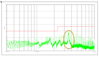
we are using the ADM2687 in our design and we see "quite some noise" from the chip in TEM cell near field measurement.
For this reason are very interested in the ISOW1412 and ISOW1044 chips as they are less expensiv and potentially less problematic.
I heard general comment from EMC compliance test house that the TI chips isolation chips cause less clients to fail tests if clients do not follow application notes :-)
In our case it seems like we have done the routing ok, as the measurement is below the limits. However we would like to evaluate the two chips from TI too, as they seem to be available again in quantities.
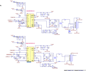
Analog device recommends Y capacitor and Extending the ground and power planes on an interior layer into the isolation gap of the PCB to form a capacitor. Can you pls give me further design guidance/advice.
I do not see any of this in TI reference design or datasheet? Is there anybody having EMC measurements (emission measurement e.g. CISPR32).
https://www.ti.com/tool/TIDA-010938
https://www.ti.com/tool/ISOW1412DFMEVM
Do you have any CISPR 32 emission measurements of the two chips and detailed info about the layout?
Best Dani