This thread has been locked.

If you have a related question, please click the "Ask a related question" button in the top right corner. The newly created question will be automatically linked to this question.

LM5180: LM5180 design requirement

Part Number: LM5180
Other Parts Discussed in Thread: LM5017,

Tool/software:

Hi guys 

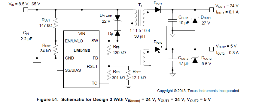
I have requirement about 4 output for  iso  Voltage:  12V/12V/5V/5V[100mA/100mA/50mA/50mA]

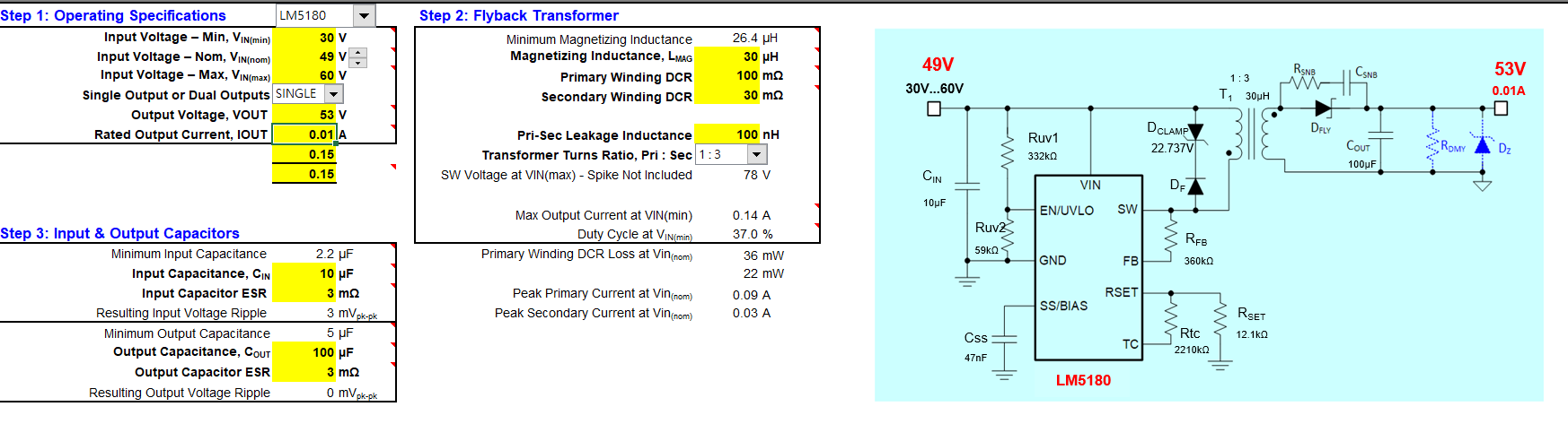
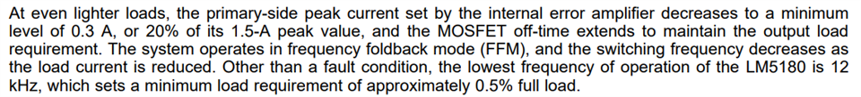
is that possible use design 3 ? there is 1 to 4 constructure ? is that power comsumption smaller than LM5017 when there is light load? 

how to I design the value for LM5180 ? 


  • Hi Frank,

    Thank you for reaching out. I would recommend LM5180. You are right that with the LM5180 the light load efficiency should be higher under light load. Please use our design calculator at the following link to help you design. There will be two steps:

    1. Use the calculator to design two output rails by merging the like outputs to one, namely 12V@0.2A, and 5V@0.1A.2. 

    2. Once you get a design, split each of output rails to 2 by simply duplicate the secondary winding and corresponding circuits.

    https://www.ti.com/tool/LM5180DESIGN-CALC

    Hope this clarifies.

    Best Regards,

    Youhao

  • Hi YouHao 

    I think I would like to be simple 

    It's that possible for LM5180 Input : 30~60V   out 53.25V??

    Here is the Design caculator ib pic below

    Could you modify us a Demo board for requirement?

  • Hi Frank,

    Yes you can order an EVM and modify it for a quick evaluation. Sorry I don't have such a transformer in hand. You will need to find a suitable transformer, and you may also need to change Dfly and Cout to support your 53 voltage ratings.    

    Thanks,

    Youhao

  • HI Youhao

    I want to know

    1. waht component decidet the output Voltage different?

    2. because I modify those component for Excel suggest and there have 59V output but When I load 0.001A

    it dorp quicky to 0V, and idea or tips ??

  • Hi Frank,

    1. The transformer turns ratio, RFB and RSET determines Vout.  If RSET=12.1k as recommended, then the other parameters satisfy the following equation:

    2. You cannot use the EVM transformer.  It has a turns ratio of 3:1, while you need a turns ratio of 1:3.  Please find a proper transformer.

    Hope this clarifies.

    Regards,

    Youhao

  • Hi Youhao 

    1. what is the Dclamp function, is it effect the Vout Voltage?

    2. Is that output Zener could removable? 

    3. Rtc value will change the output Volatge?

  • Hi Frank,

    I will get back to you next week.  Currently we are off for the holiday and please do not post here until next week.  I am writing this on my mobile phone. Thank you for understanding.

  • Hi Frank,

    1. The Dclamp replaces the usual RCD snubber to cope with the turn-off voltage spike on the internal FET.   The voltage rating should be greater than the reflected output voltage, namely Nps x (Vout+VF), then it will not affect Vout.

    2. The output Zener is introduced to cope with No load conditions. It can be used with or without Rdym, which is the dummy load.  The device has a min load requirement:

      To estimate the min load:  Pmin=0.5 x 12kHz x Lmag x (0.3A)^2. 

    If the min load is not met, Vout will rise and the Zener would clamp and prevent Vout to be excessive. Yes it can be removed if you have the dummy load to cover the min load condition. 

    3. Rtc is introduced to stabilize Vout over temperature.  If not used properly, yes it will change Vout setting point. 

    Hope this clarifies.

    Best Regards,

    Youhao